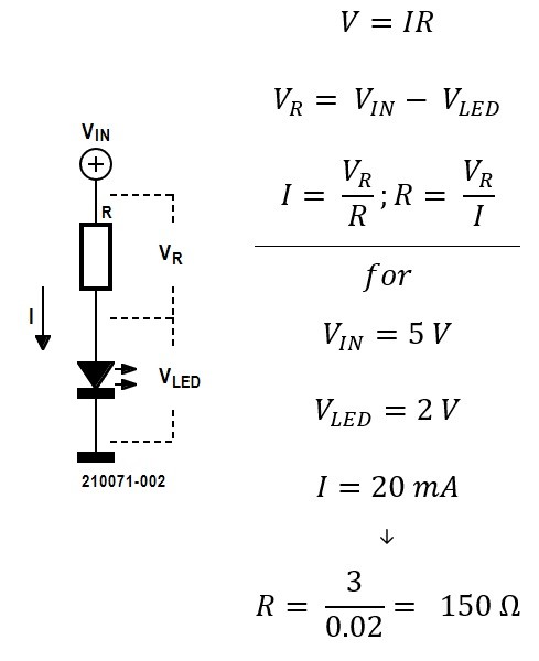
LEDs are a staple component in most circuits. Using Ohm’s law, we can easily calculate the conditions for the theoretical lighting intensity we’re after.
LEDs are a staple component in most circuits. They’re used to light things up or to indicate something to the user from within the hidden and obscure bowels of a component. Many would be familiar with the simple power-resistor-LED-ground circuit for lighting up an LED. Using Ohm’s law, V = IR, we’re able to calculate the appropriate value of the current limiting resistor given the driving voltage and the desired current for the LED.
Using Ohm’s law we can easily calculate the conditions for the theoretical lighting intensity we’re after.
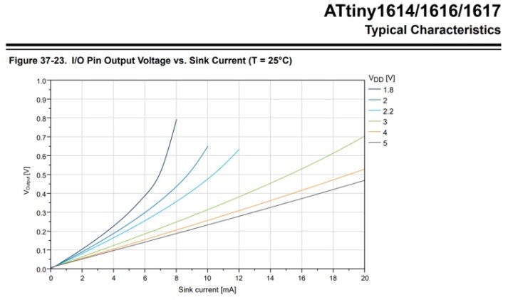
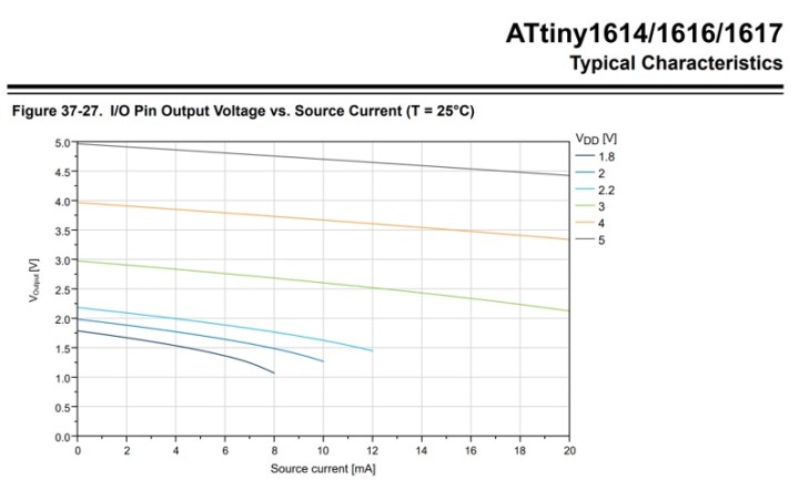
Simple enough. But as always, physics, and a bit of specsmanship, derail our otherwise ideal calculation. If we’re driving an LED from a microcontroller, which we often do, then the driving voltage and "ground" may not be what we punched into V = IR. If you look carefully at the microcontroller’s input-output (IO) pin specs, you’ll notice that there is a relationship between increased current and output voltage. If you’re sinking current, ground goes higher than zero; when you’re sourcing current, voltage goes below the ideal. If you’re driving an LED between two IOs, like when multiplexing several LEDs, you’ll experience both lower voltage and higher ground! The specs for these voltages also vary with temperature, but not as much. (While you’re with the datasheet, make sure that the IOs can actually supply the current to drive your LEDs, and that you’re not exceeding the total amount of current you can ask of the micro to source and sink. That’s important stuff to pay attention to.) Refer to the Microchip Technology datasheet, "tinyAVR 1-series: ATtiny1614/1616/1617," DS40002204A, 2020.
The IO output voltage of Microchip’s ATtiny161X. As more current that goes into the IO, the higher the output voltage compared with ground. (Source: Microchip Technology)
The IO output voltage of Microchip’s ATtiny161X. As more current is demanded from the IO, the lower the output voltage compared to the ideal voltage. (Source: Microchip Technology)
Then, LED manufacturers, sometimes deliberately, define specs in a way that makes it hard to compare the perceived intensity of the LED with their competitors’ products, or even within their own ranges. So, even if we try real hard to compare them by specification alone, we may still be surprised when we plug them into our circuit. On top of all that humans perceive intensity differently.
It’s great to be prepared with all this knowledge, but does it matter in practice? Not really; you’ll still need to test the LEDs and fine-tune your resistor values in-circuit, no matter how hard you try to predict the shine. This is what I always do. I’ll order — or, better, ask for free — samples of a dozen or so candidates and test them under my circuit’s conditions to see what works best. I haven’t found a better way so far. Have you?
Additional Circuit Shorts, Info on LEDs, and More
Interested in circuit design, LEDs, and PCBs? You can subscribe to the "Circuit Shorts" tag to receive updates. If you are Looking for a rapid prototyping solution, check out ElektorPCB4Makers. Get two PCB prototypes in three working days!
Elektor Magazine has been one of the leading sources of information on electronics for engineers, designers, start-ups and companies for 65 years. Our magazine is powered by an active community of electronics engineers – from students to professionals – who are passionate about designing and sharing innovative ideas.
For them, we publish hundreds of items a year, in formats such as articles, videos, webinars, and other learning formats. Our mission is to share knowledge in every possible way and inspire readers with the latest developments within the electrical engineering sector.
Thank you for your vote!
Leave further comments in the fields below.
Thank you for your vote!
If you wish to leave a comment with your rating, please first use the login below. If not, just close this window.


Discussion (0 comments)