
MiniPhonic: An Arduino-Based Audio Synthesis Platform (2)
on
Thanks to software frameworks and libraries that have become quite powerful over time, even with a compact and inexpensive system, it is possible to achieve complex functions. In the first part of the MiniPhonic article series, we've described the block diagram and the main functions of the Basic Synth software. Here we conclude with the description of the Sequence application and firmware, taking a look at the hardware of the main board and display board, including assembly instructions and component list. Let's get to work!
Sequence
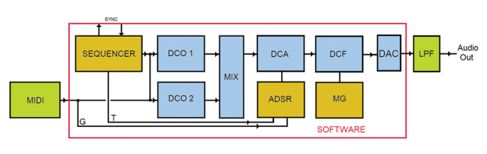
This application is also based on Tim Barras’s Mozzi library, and uses a modified version of Staffan Melin’s OscPocketO software, which allows some parameters to be changed in real time. The block diagram of the Sequence application is shown in Figure 1. The main features are as follows:
- 16-note sequencer with 4 patterns, which can be expanded if required, also with output on MIDI OUT.
- Sequences are displayed in alphanumeric musical notation (e.g. C, C#, D…).
- Two wavetable oscillators DCO1 and DCO2 with five waveforms that can be replaced.
- Second oscillator with Detune and Transpose.
- Envelope generator with four parameters, ATTACK, DECAY, SUSTAIN LEVEL and RELEASE that can be controlled in RT via pots.
- LP filter with adjustable Frequency and Resonance.
- Filter modulation generator with selectable Slow, Fast and Random parameters.
- 4 recallable panels, expandable if necessary.
- Possibility of using an external keyboard via MIDI IN to play in real time.
The main module of this application is the SEQUENCER. With it, you can produce sequences of notes that are repeated cyclically, stored on 4 patterns of 16 notes each, residing in EEPROM and therefore non-volatile.
For each note, you can vary the pitch, i.e., the MIDI note number and its state: STATE_OFF mutes the note, thus performing a pause, STATE_ON plays the note at normal volume, STATE_BOLD plays the note with an accent.
It is also possible to transpose the entire pattern up or down, to adapt it to the desired key, without having to modify all the notes. The sequencer also has a SYNC input/output, thus allowing one or more synthesizers to be connected in parallel.
The sequencer controls the two oscillators DCO1 and DCO2, which also accept data from the MIDI port so that you can play in real time, regardless of the sequencer. The MNU+ and MNU- buttons take you into the menus.
Let’s take a closer look:
SEQUENCE: operating the VAL+ and VAL- buttons starts or stops the sequencer.
SYNC: activates synchronization, which can come from inside or outside, via the appropriate connector. EXT24 item is used to synchronize sequencer at 24 ppq (Pulses per quarter note; 140 bpm max.).
PATTERN: VAL+ and VAL- allow you to choose from the four available patterns.
ED pat: allows you to edit the pattern; use LEFT and RGHT buttons to move over notes, press VAL+ and VAL- to change the note which is expressed n alphanumeric notation, i.e. on the third line of the display the notes are shown according to the international standard: C, C’ (C sharp), D, D’ (D sharp), E, F, F’ (F sharp), G, G’ (G sharp), A, A’ (A sharp), B. The number below indicates the octave in which the note sounds.
STATE: state of each note; again we can move to the notes with the LEFT and RGHT buttons, and through VAL+ and VAL- we can change the state of the note
- = mute
O = note played normally
B = accented note
TEMPO: metronome expressed in bpm.
GATE: note length expressed in percent; for example, a value of 30 makes the note sound with a duration of 30% followed by a pause of 70%.
SH pat: moves the entire pattern up or down by pressing VAL+ and VAL- one semitone at a time.
WAVEFORM: allows using VAL+ and VAL- to choose from five waveforms for DCO1: Sin = sine, Tr = triangular, Saw = sawtooth, Square and an atypical one called Phasor.
FILTER mode: again using VAL+ and VAL- we can change filter operating modes: Fixed in which the cutoff frequency of the DCF gMFilterCutoff, is manipulated by potentiometer, Random where the frequency is shifted randomly and with speed set by MG1, Man.Mod in which a triangular shape modulation is applied with speed always set by MG1 and finally Fast, like the previous one but with fixed speed. MG1 can be reached from the panel mixer, entry FRM1.
WAVEFORM2: Allows, via VAL+ and VAL- to choose from five waveforms for DCO2: Sine, Triangular, Saw, Square and the atypical Phasor.
DETUNE2: Allows, via VAL+ and VAL- to slightly detune the frequency of DCO2: a value of 2 generates a very pronounced chorus effect.
TRANSPOSE2: VAL+ and VAL- transpose DCO2 with respect to the MIDI note number.
KEY PLAY: immediately plays the first 4 notes of the current pattern by pressing the four buttons LEFT, VAL-, VAL+ and RGHT. The corresponding MIDI note number is indicated above each button. Useful for rehearsing sounds or playing in real time, especially when there is no keyboard connected.
TOOLS: S saves the current configuration including patterns in nonvolatile memory, L loads previously saved configuration and patterns, R creates a random sequence in the current pattern, B creates a monodic bass line (same note) but with all notes in O state so you can easily change it.
Again, the P function allows a choice of 3 panels, main, adsr and mixer, respectively.
The Sequence Firmware
In the setup (around line 1520), we find all the instrument settings and the necessary initializations. More specifically, the pins are configured and the display is started with the command:
gUILCD.begin(20, 4)
Next, some custom characters are created, not included in the default LCD set, which are useful for displaying the pattern sequences:
gUILCD.createChar(0, Dodiesis);
gUILCD.createChar(1, Rediesis);
gUILCD.createChar(2, Fadiesis);
gUILCD.createChar(3, Soldiesis);
gUILCD.createChar(4, Ladiesis);
Next, we find the credits and version numbers of the software and the MIDI initialization preceded by connections to the MIDI library of HandleNoteOn and NoteOff:
// Connect the HandleNoteOn function to the library,
// so it is called upon reception of a NoteOn.
MIDI.setHandleNoteOn(HandleNoteOn);
// Put only the name of the function
MIDI.setHandleNoteOff(HandleNoteOff);
// Put only the name of the function
// Initiate MIDI communications, listen to
// all channels
MIDI.begin(MIDI_CHANNEL_OMNI);
You may notice that there are several NOTE ON functions. The main function is playNote(), located around line 420, and is used by the sequencer. The playNoteOn() function, on the other hand, is specific to KEY PLAY mode, which allows you to play the first four notes of the current pattern using the LEFT, VAL-, VAL+, and RGHT keys.
Finally, the HandleNoteOn() function is used to handle inputs from the keyboard connected to the MIDI IN port.
Of course, there are also two reciprocal functions that end the note being played, playNoteOff and HandleNoteOff, respectively. At 1570, we find the declarations and the connection of these functions with the MIDI library.
From around line 1580, all the Mozzi library settings follow, so that the synthesizer can start playing immediately; similarly (around line 1610), the Sequencer settings follow.
The user interface (User Interface Draw) is started around line 1630 with the UIDraw() function, and immediately afterwards the Mozzi library startMozzi(CONTROL_RATE) is started.
Let’s now move on to the updateControl() function found on line 1640, where all the controls are implemented, and immediately afterward we find the MIDI port query in case a keyboard is connected:
if(MIDI.read()){
gMEnvelope.noteOn(); // play from MIDI input
PanelHandle(); // handle panel
}
The PanelHandle() function allows you to modify the parameters managed by the four potentiometers, as already seen for the Basic Synth. This is followed by the sequencer engine (around 1648), where synchronization is first handled and then the program checks whether the current sixteenth note has elapsed before moving on to the next note.
if (gSyncNoteOn) {
playNote();
gSyncNoteOn = false;
Here too we find the PanelHandle() function so that we can make parameter changes every time a note is played, followed by the processing of the next note, until the maximum number of notes is exceeded, at which point we return to the first note.
PanelHandle(); // --- Sequence/Mozzi
gSeqNoteIndex++;
if (gSeqNoteIndex >= MAX_NOTES) {
gSeqNoteIndex = 0;
}
}
The note duration is then checked and the Off note and sync out are called for any external devices, and the envelope is updated with gMEnvelope.update().
At this point, the User Interface is called to see if any keys are pressed with gMEnvelope.update().
Finally, the audio update updateAudio() follows. This is the most important function as it encompasses the processing of the audio stream, as already seen for the Basic Synth. In fact, the switch
switch(gSeqStatus[gSeqPatternIndex][NIdx])
establishes the gMGain level, i.e. the volume of the note being played, which will then be used by SYNTHESIZER CHAIN 2 (visible in the respective frame in this article). The loop containing the main call to the Mozzi audioHook() library concludes the program.

Practical Realization
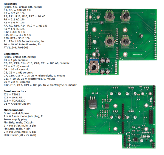
Using the PCB images of the component lists as a reference, it is advisable to begin assembly by starting with the SMT (surface-mounted) components on their respective soldering sides, beginning with the passive components. Next, you will proceed with the assembly of the TH (through-hole) components on the opposite side.
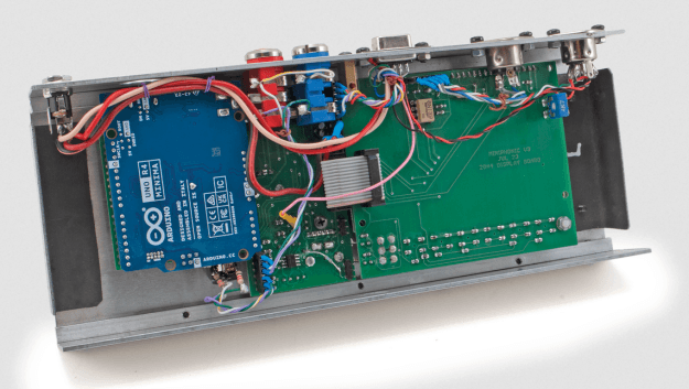
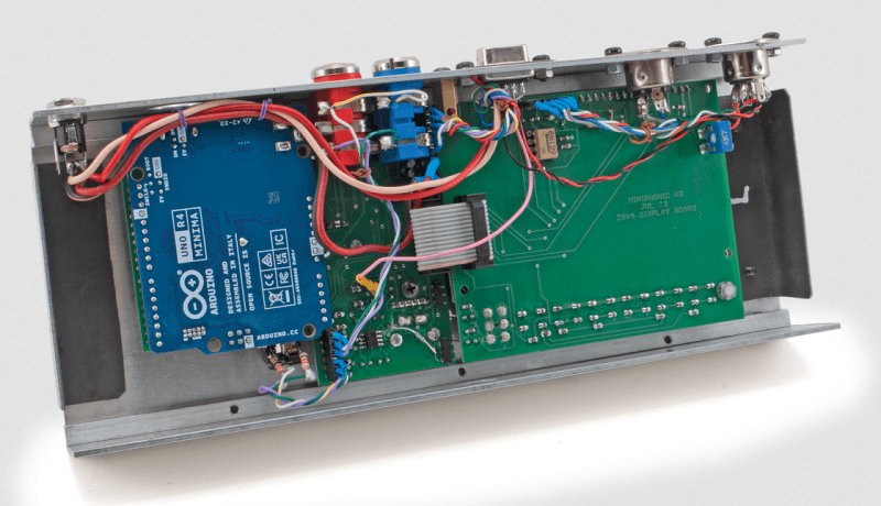
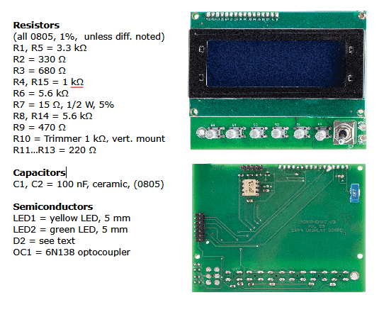
It is advisable to enclose the MiniPhonic in a case, as shown in the intro image for this article and in Figure 2. In it, you may notice the arrangement of the main board (see the schematic in Figure 3) and the display board (Figure 4), connected through a flat cable.
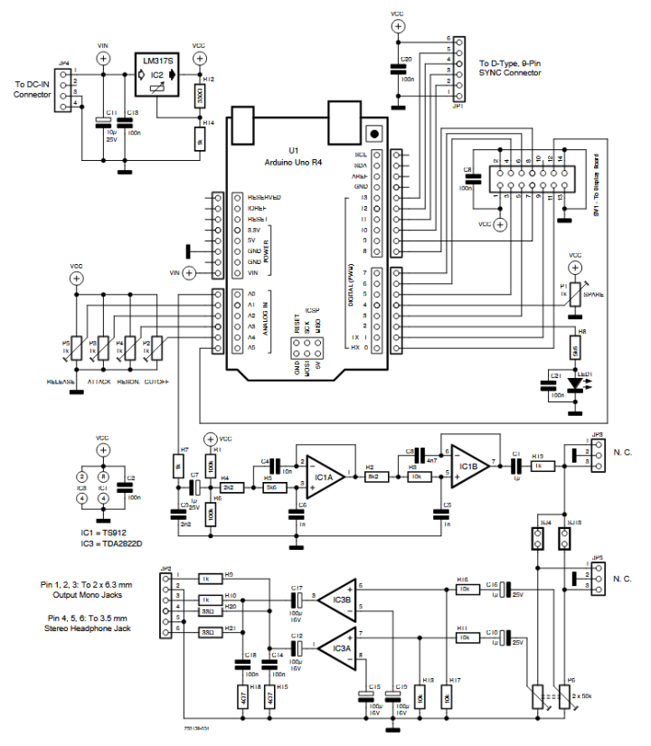
IC3 is a TDA2822D Audio Amplifier by STMicroelectronics, whose output is sent to both the 6.3 mm L and R female mono output jacks and to the headphone 3.5 mm stereo output jack on the rear side of the MiniPhonic’s housing.
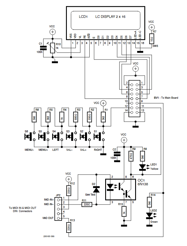
The potentiometers and knobs used are commonly available. The first potentiometer at the top left of the Main Board picture (see Component List Main Board text frame) should not be mounted.
Special attention should be paid to the SYNC connector and, in particular, to the AUDIOBUS connection, highlighted in green in the wiring diagram of Figure 5. If multiple synthesizers are connected in parallel, all audio channels must also be connected in parallel; however, it is important to note that the overall output will decrease by 6 dB, due to the load represented by the other connected synthesizers.
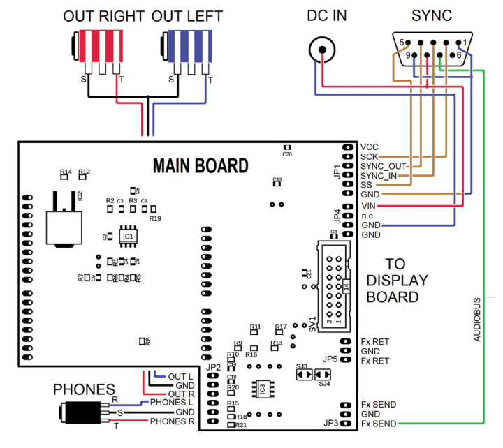
If you prefer to use a mixer (recommended solution), it is advisable to disconnect the AUDIOBUS from the connector, possibly equipping it with a switch, so that each synthesizer has its own channel. The same SYNC connector also provides power from the DC IN connector, allowing the use of a single power supply (wall transformer) for all synthesizers. It is important to consider that each synthesizer draws approximately 200 mA.
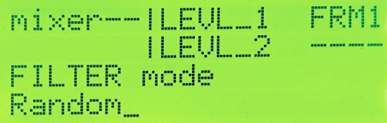
Figure 6 shows the name of the current panel — in this case mixer — followed by three parameters: LEVL_1, LEVL_2, and FRM1, as well as a blank space. These parameters are assigned to potentiometers P1, P2, and P3, respectively, while P4 remains unused in this panel. The LEVL_1 and LEVL_2 parameters adjust the level of the two oscillators, while FRM1 controls the frequency of MG1. This panel is part of the Basic Synth.
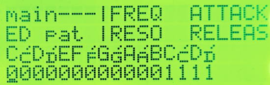
Figure 7 shows the main panel with the ED PAT menu. The third line shows the sequence of notes, while the fourth line shows the respective octaves. The first note is a C in octave 0, followed by a C# (C sharp) in the same octave, then a D, also in octave 0, and so on. The sequence ends with a D# in octave 1.
MiniPhonic Platform: Final Considerations
The MiniPhonic platform, besides allowing the development of small synthesizers and learning the basics of sound synthesis and MIDI protocol, is also suitable for further development. For example, the SYNC connector is arranged to carry SDI, SDO, SCK, and SS signals externally, allowing for an SPI data stream. This stream could be used as a carrier for a multichannel audio and related control signals, which can be exploited to implement external components such as analog VCFs, VCAs, and other devices.
Thanks to the power of the ARM processor, one could expand the Basic Synth to make it polyphonic, say 3-voice, while maintaining the current structure. The applications described above, moreover, are open to further reworking and improvement, with the aim of exploiting the full potential of the ARM processor.

Here, the filter, originally designed for the Arduino UNO R3, which is the weak link in the chain, deserves a mention. When RESONANCE is brought to maximum, the filter becomes unstable and tends to oscillate, introducing considerable distortion. In our opinion, this component should be the first element to be redesigned. However, credit should be given to the designer of the current version, who managed to run the system on an Arduino UNO R3, a remarkable achievement!
The complete software package for the MiniPhonic project is available for download at its respective Elektor Labs page.
Questions About the Miniphonic Project?
Do you have technical questions or comments about the MiniPhonic project or this article? You can contact the editorial team of Elektor at editor@elektor.com.
Editor’s note: The MiniPhonic audio synthesis platform project originally appeared in Elettronica IN.
![]()


Discussion (1 comment)