
DVI on the RP2040 MCU: A Q&A with Raspberry Pi's Luke Wren
on
The Raspberry Pi RP2040 is a sub-$1 MCU with amazing capabilities. One of its engineers is Luke Wren, who has also shown that the small RP2040 can do DVI output. (Refer to the article, “Video Output with Microcontrollers (2)”). If he’s not working on secret projects for Raspberry Pi, he shares some of his leisure projects with the community on Twitter (@wren6991) and the code on GitHub.
Mathias Claussen: Can you tell us a little about yourself?
Luke Wren: Starting with the hardest question! I’m an engineer at Raspberry Pi, and when I’m not doing that, I’m usually working on my hobby projects, playing guitar badly, or, more recently, putting time into language learning. I live in Cambridge, UK, not because it’s a particularly exciting city, but more because of inertia after graduating from university. I lived in Germany when I was younger, but my German is pretty rusty these days, so I’m glad we’re doing this in English.
Mathias: How long have you been with Raspberry Pi?
Luke: I joined as an employee in September 2018, but I interned at Raspberry Pi previously.
Mathias: What was your role in the development of the RP2040?
Luke: I worked on some of the digital design — mainly PIO, DMA, XIP cache, bus fabric and PWM. I also worked on the boot ROM and the SDK, and, of course, I had to pitch in for the documentation as well.
Mathias: Getting video from an MCU/CPU is something the Sinclair ZX81 could do, but DVI is something new for a sub-$1 MCU. While VGA output can be done by most MCUs, what is the challenge with DVI?
Luke: There are two things that make DVI-D harder than VGA. The first is serializing the data: The minimum pixel clock for DVI-D is 25 MHz, and the bit clock is 10 times that, so, at a minimum, you are driving 3 × 250 Mbps differential serial lines (red/green/blue). The second is that DVI-D does not just send raw pixel data, but encodes it first. The encoding is simple in hardware, but a bit fiddly in software, especially when that software has to keep up with the raw speed of the serial output. Everything else is similar. It really is just DPI through a faster pipe. (Editor's note: Display Pixel Interface is a parallel RGB pixel interface — including a pixel clock — to transport pixel data to a display device).
Mathias: What was your motivation to try DVI on the RP2040?
Luke: Once the stress of silicon bring-up had passed, a couple of us wanted to see how high we could push the system clock frequency. There is, in practice, some margin over the 133 MHz rated frequency. I had been playing with DVI-D on FPGA, as part of my RISCBoy project, and when I noticed that there was an overlap between the lowest DVI bit clock frequencies and the highest system clock frequencies on RP2040, a lightbulb went on in my head. The motivation was, “I wonder if this is possible.”
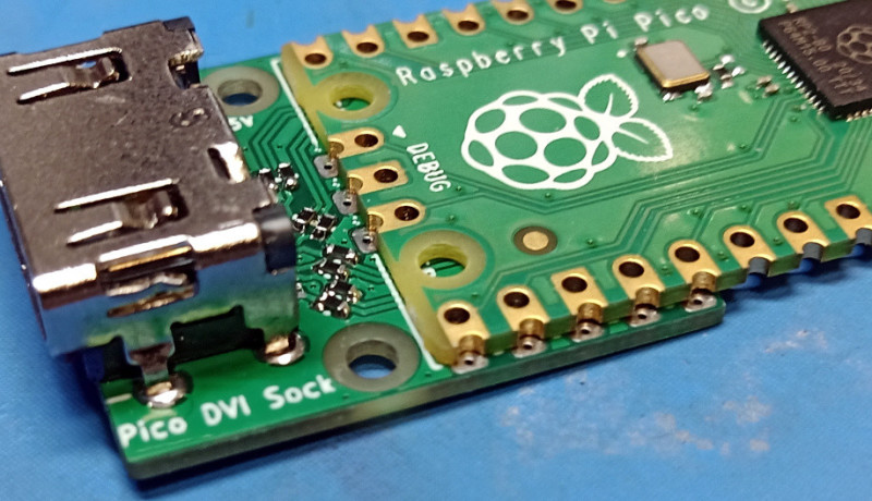
Mathias: What was the most challenging part of getting a DVI output (Figure 1) on the RP2040?
Luke: TMDS encode. If you follow the algorithm in the DVI specification, there is no hope of getting it fast enough on two Cortex-M0+ cores running at the bit clock frequency. So, there are some tricks and shortcuts to make it possible, and then some carefully handwritten code to make it usefully fast. The RP2040 has a lot of memory, but not enough to store a frame’s worth of TMDS-encoded pixels, so you do have to “race the beam” during encoding.
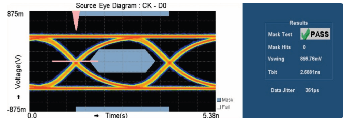
Mathias: You had to overclock the RP2040 slightly (from 133 MHz stock to 252 MHz). Is there a critical path in the chip for the DVI signals (you need to drive I/O pins with speeds that are also faster than stock speed)?
Luke: The first constraint you will hit on the RP2040 is that the system clock has to be 1:1 with the bit clock, so if you try to go to higher-resolution modes, then the processors are just going to crash. The critical setup path for the system clock domain on the RP2040 is processor address-phase signals into SRAMs. That said, we’re also pretty close to the limits of what you can drive through those general-purpose 3V3 pads; if you look at the eye mask (Figure 2) for 720p30 (372 Mbps) on my GitHub, it passes, but it’s marginal. I doubt you’d see 1080p30 without dedicated hardware.
Mathias: Besides the speed increase, how crucial are the PIOs and the interpolator inside the RP2040 to get DVI working?
Luke: It’s a hard requirement that you need to present 3 serial data bits, plus their differential complements, on GPIOs at 250 Mbps minimum. Being able to do the single-ended to pseudo-differential conversion in the PIO cuts the DMA bandwidth in half, and having the TMDS lanes split into 3 FIFOs is useful if you’re doing the encoding in software because it lets you specialize your code for the encoding of the red/green/blue components. So, something like PIO is crucial if you don’t have dedicated hardware. The interpolators help with address-generation performance in the TMDS encode, which is certainly key to some of the demos you have seen, but my pixel-doubled TMDS-encode trick would still fit onto a single Cortex-M0+ core without the interpolators.
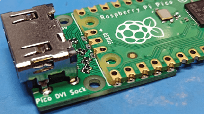
Mathias: Your Pico DVI Sock for the RP2040 uses a physical HDMI connection (Figure 3), clearly labeled as DVI-only, so we won’t get audio. Is it “just” a licensing issue with the HDMI consortium?
Luke: There is nothing stopping you from adding HDMI data islands and doing audio output. In fact, someone has done it with an NES emulator port! a> There are no extra physical connections required for the audio signals, although, strictly speaking, you are not supposed to use HDMI features before interrogating the display data channel, which is not hooked up on my Pico DVI Sock. The HDMI licensing situation is certainly a can of worms I don’t want to open, and I also backed myself into a corner by calling the repository “PicoDVI,” so I’ll leave this one to the community.
Mathias: When using the DVI output, how much of the RP2040 resources are bound to that task? Is there time to spare to run other code on the MCU?
Luke: It depends on the video mode. Say, for pixel-doubled RGB565 output, you end up spending around 65 % of one core for TMDS encoding and DMA interrupts, and the other core is then fully available for generating the video and running your main program logic.
Editors note: Besides the pure video generation, some applications for the Pico DVI Sock were added. One being the moving several Eben Upton faces around the screen. If we do some math, having a 640×480-pixel image stored as a full frame with 8-bit resolution would take ~308 KB of RAM (more than the RP2040 has), so we fix it at a max of 320×240 with 16-bit color (154 KB) in RAM, but the demo (Figure 4) is not pixelated that way. So, there seems to be some software trickery involved.

Mathias: With the software to generate a DVI signal comes a library that also handles sprites. Can you talk more about it?
Luke: Sure! So, when you write a video output, the very next problem you come across is needing to have some video to actually output, and the ARMv6-M sprite library is something I hacked together whilst working on PicoDVI for exactly that purpose. The critical feature of this library is that it does not require a frame buffer to render into, just a scanline buffer. Your rendering races the beam, just ahead of the TMDS encode. This means you can support video output resolutions that would not fit into memory as a flat frame buffer, and it leaves most of your memory free for the actual graphics assets. There are some reasonably fast blit and fill routines, some tiling routines, and some affine transformed sprite routines that let you do scaled/rotated/sheared sprites. Enough for some games on the level of a Game Boy Advance or so. (Editor’s note: You can see an example in Figure 5.)
Mathias: Where did you get the inspiration for the library — and the time to write it?
Luke: I spent some time working on scanline-based graphics hardware for RISCBoy, so, having done that in hardware, it was fairly easy to replicate it in software. Everything in the PicoDVI repository was done in my spare time on my laptop, except for the eye diagrams, which used a scope at work.
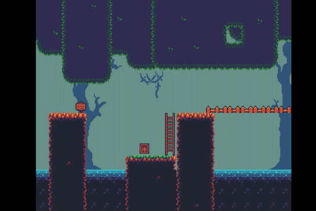
Mathias: There is a Zelda-inspired Sprite demo for the RP2040 (Figure 6). Can you tell us about the idea behind that? An NES or SNES would use dedicated hardware to compose images like that, and here we have just two CPUs moving pixels.
Luke: That is actually a port of one of the RISCBoy demos. Like you say, there is a lot of overhead in doing all of this in software, and RISCBoy running at 36 MHz can put as many sprites on screen as the RP2040 at 252 MHz.

Mathias: In the documents for the library mentioned, there’s the idea of a Mario Kart clone for the RP2040? Was it just an idea, or has tinkering started to get it working? Also, there’s mention that the interpolator would be useful for it.
Luke: So I have to cough up at this point and admit that wanting to do SNES MODE7-style texture and tile mapping is the original reason for the interpolator being in the chip, although between then and tape-out we spent some time making it a more generally useful and capable piece of hardware. We’ve never put together an actual MK clone, although you can see plenty of examples of people using similar techniques online; we did have a texture-mapped 3D cube with Eben’s face on it running on FPGA.
Mathias: In the documentation for your Pico DVI Sock for the RP2040 Pico, you mention a 48 MHz FPGA prototype. Can you tell us a little about that prototype?
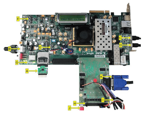
Luke: We had a nightly job to build an FPGA image from the latest RP2040 source code so that, the next day, we could use it for software development. We just used an off-the-shelf Virtex 7 development board, with a daughterboard for level-shifting the FPGA IOs up to 3.3 V (Figure 7), and another little board that puts a QSPI flash into the SD socket, which is connected to the RP2040 XIP interface. The FPGA build is pretty much a full-featured RP2040 — the clock/reset circuitry is simplified, and the ADC is stubbed out, but, other than that, it is all present and correct. This makes it an ideal platform for software development, although the actual verification of the chip used conventional simulations and formal model-checking.
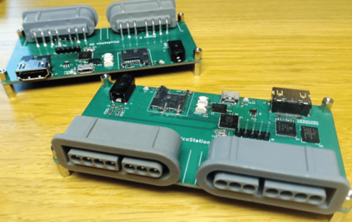
Mathias: Besides the DVI output, you are/were working on some other projects. One of those is the PicoStation 3D. Can you tell us a little bit about it? If you could source all of the parts, would it still be the same design today?
Luke: So, PicoStation 3D (Figure 8) is one of the many hobby PCBs I had in flight leading up to the RP2040 launch. It’s a board with an RP2040, an iCE40UP5K FPGA, microSD, audio out, DVI-D out via HDMI socket, and two SNES controller sockets. I was reading a lot about 3D graphics hardware at that point and wanted a platform to play with that, in the context of a small games console kind of thing. It pains me that I have left that project on the back burner for so long, but besides the parts issues, I also just have too many other projects on the go. It’s all open-source, so I would love it if someone else picked up the idea and ran with it. I think the choice of FPGA is just about right — it’s small and slow enough to make you work hard for your demos, just barely DVI-D-capable, and it has generous onboard memory and a handful of 16-bit DSP tiles, so it’s a brilliant platform to play with toy graphics hardware. It also pairs up well with RP2040. What I would like to spend time thinking about is the IO. For example, what if you moved the DVI across to the microcontroller and moved the SNES controllers across to the FPGA, and what if you made the audio circuit a little better, that kind of thing. I think the physical form factor is about right, since it’s defined by the two SNES controller connectors.
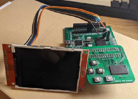
Mathias: Besides the Raspberry Pi-based items, you also did a RISCBoy, which is powered by a self-developed RISC-V Core and other peripherals, such as a graphics engine (2D-sprite-based?). Can you say some words about this development?
Luke: RISCBoy is my slightly belated competitor to the Game Boy Advance. The full-fat hardware fits into an iCE40 HX8K with some external parallel SRAM (Figure 9). Eventually, there will be a physical version, but, right now, it’s still an HX8K dev board with some SRAM and buttons, and an SPI display hanging off of it (Figure 10). I started working on it around the time I left university.
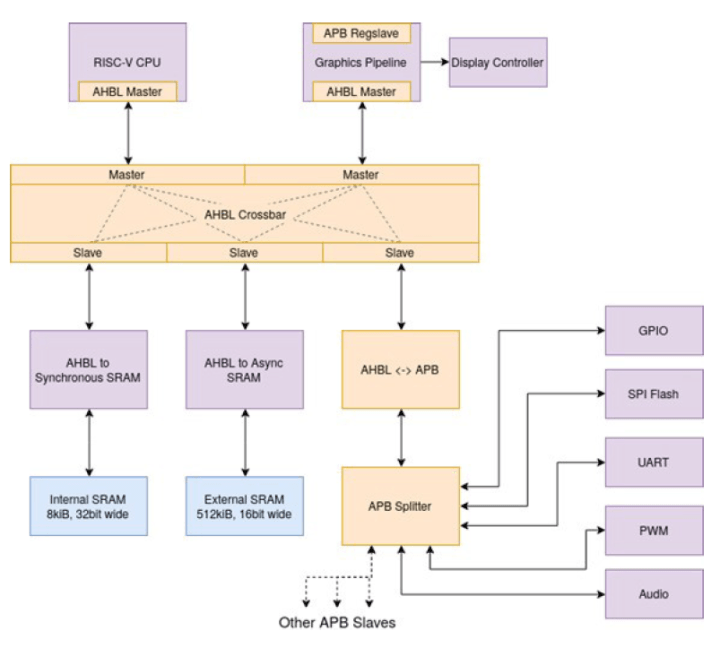
Everything is unapologetically written from scratch — not a good way to do engineering, but a great way to learn, and it makes debugging more fun when there’s not a single part of the hardware/software stack that you can trust. There’s a 32-bit processor (Hazard5), some programmable 2D graphics hardware, and all the infrastructure to tie it together. The graphics hardware does all of your usual sprites, tiles, affine-transformed sprites/tiles, and so on, but it does this by executing, from memory, command lists that provide limited support for control flow and branching to subroutines. During each frame, the processor is writing out the command list for the next frame. There are a pair of scanline buffers in hardware, one that is being rendered into, and one that is being sent to the display, so you avoid the bandwidth, latency and memory footprint costs of rendering into a frame buffer. It’s on the back burner for now, but definitely a project I intend to finish one day.
Editor's note: This is an abridged version of an interview with Luke Wren. Read the full interview in Elektor March & April 2023.
Discussion (0 comments)