
ESP32 Audio Transceiver Board (Part 1): SD Card WAV File Player Demo
on

ESP32 controllers are well-like solutions used in thousands of IoT, smart home, and other remote control projects. The ESP32 has also a good I2S interface, which can be used to output and input digital audio signals. In combination with an I2S DAC, an I2S ADC, and an SD card, many kinds of audio projects are possible. In this project, we integrate all this, together with a nRF24 transceiver for transmitting and receiving (audio) data, on a solder-friendly PCB. In the first part of this article series, we present the block diagram, circuit, and demo software.
The Choice of ESP32
The popular ESP32 controllers are affordable, fast and easy to program — for example, with the Arduino IDE. Equipped with Wi-Fi, they are used in thousands of IoT, smart home, and other remote control projects, and we can hardly count the Elektor projects of that kind. However, ESP32 controllers have also built-in a good I2S interface, which can output and input audio streams digitally. (Refer to the "I2S Interface" section below.) What you additionally need for playing audio is an I2S DAC that takes the I2S data from the ESP32 and transforms it into an analog signal. For the other way round, sampling audio, you need an audio ADC with an I2S interface. For this project, we put an ESP32-S3 based development module together with an I2S ADC/DAC breakout board on a carrier PCB. We also integrated an option to plug on a Nordic nRF24 wireless module to transmit and receive digital (audio) data. An SD card, several extension connectors and different power supply options complete the audio transceiver project.
I2S Interface
The I2S interface and protocol for transmitting digital audio data (has nothing to do with I2C) is well documented in the Internet [9], so we don't have to waste too many sentences about the basics. Audio data are transferred bitwise on one wire, where another wire is used as the bit clock for this transmission. Another wire is used to separate data for the left audio channel from data for the right audio channel. So, you need at least three wires between the microcontroller and the I2S DAC or ADC (besides VCC and GND to supply these chips).
To ensure that the microcontroller and the DAC or ADC are clocking synchronously, there is another connection foreseen, called “Master Clock”. Many sources on the Internet and also my own experience tell that, using an ESP32, the ESP32 should act as the clock master and the DAC or ADC as the slave, and not vice versa. Therefore, the I2S2 Pmod module (hosting a DAC and an ADC) we use in this project must be configured as slave, with a jumper connection at the right place.
Use Cases
This audio transceiver board is mainly dedicated for audio applications, but you also can use it to sample/output/store/transmit/receive other signals and data. Here are some use cases, and we will implement some of these in upcoming articles.
- Audio player playing files from SD card (see demo software below)
- Audio recorder
- Audio processor (sampling audio, do something with the data, and outputting it)
- Audio wireless sender/receiver via Wi-Fi or ESP-NOW
- Audio wireless sender/receiver via Nordic nRF24
- Datalogger: sensors connected via SPI/I2C, data are stored on SD card
- Wireless sensor node: transmitting sensor values via Wi-Fi or nRF24
- Generating or measuring LF signals

Main Blocks
You can see the blocks and connectors of the ESP32 Audio Transceiver in Figure 1.
ESP32-S3-DevKit-C
The brain of the audio transceiver project is the ESP32-S3-DevKit-C Board with 44 pins; it will be plugged in the center of our PCB. Basically, the DevKit-C board integrates a ESP32-S3-WROOM module (with a 2-core ESP32-S3 processor), maker-friendly DIL extension connectors and two USB connectors for programming and power supply (see Figure 2). Please note that there are several pin-compatible S3 DevKit-C variants on the market. Some are hosting a WROOM-module with a printed PCB antenna, some a WROOM-module with a connector for an external antenna. The latter makes it possible to put our carrier board together with the DevKit in a metal housing, and still use the Wi-Fi functions of the ESP32.
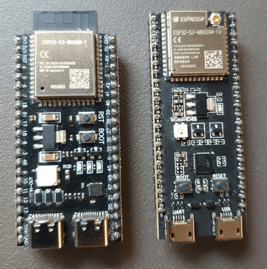
and two USB-connectors for programming and power supply. On the left a version
with PCB antenna and 1“ width. On the right, the version from the Elektor Store,
with 0.9“ width and connector for an external Wi-Fi antenna.
As there are S3-DevKit-C-variants with a width of 0.9“ and 1“, we made our carrier board suitable for both, with an extra pin-header. If you use a 0.9“ wide ESP32-S3-DevKit, the outer pinheader (J3) can be also used as an extension connector.
An S3-DevKit-C with PCB antenna is available for about €8; it can be plugged and swapped easily. The only thing you have to solder are two rows of headers. However, we are already thinking on a second version of our PCB, with the S3-WROOM module directly soldered on it, which will save space and even more costs.
I2S DAC/ADC
There are many I2S breakout boards for sampling and playing audio on the market. At the end, we decided for a Digilent I2S2 Pmod module, hosting a Cirrus CS4344 DAC (up to 192 kHz/24 bit) and a Cirrus CS5343 ADC (up to 96 kHz/24 bit), both connected to stereo audio jacks (Figure 3). Basically, it is two breakout-boards in one. At the 2x6 connector there are two independant I2S interfaces accessible, one for outputting and one for inputting audio (see textbox I2S interface). The VCC and GND pins for the power supply are also double. It is a bit unusual that this 2x6 connector stands horizontally, but that is part of the Pmod connector specification from Digilent. To plug this module on our PCB, you have to solder an angled 2x6 receptable.

and a Cirrus CS5343 ADC, both connected to stereo audio jacks.
On our board, the 2x6 Pmod connector is routed to GPIO35 to GPIO40, plus GPIO47 and GPIO48. Of course, nothing hinders you to connect here other Pmod modules (current sensors, audio amplifiers, ...) or to make your own small extension board with a 2x6 connector in the usual 2.54 mm pitch.
nRF24 Transceiver
Besides the Wi-Fi and ESP-NOW capabilities of the ESP32, we wanted to offer a third option, especially tending to very low latency when sending/receiving a continuous audio stream. Nordic’s proprietary wireless protocol for their nRF24 transceiver modules is very fast. You can send packets from sender to receiver in less than 1 ms. The nRF24 chips are also used in many IoT projects, as there are quite cheap breakout boards integrating this chip, and furthermore, there are good (Arduino) libraries. The modules integrating an nRF24, an antenna amplifier and an antenna connector are especially worth the money. Our experiences show that the range inside buildings is better than Wi-Fi. One advantage is that the chips are sending in their own 1-MHz-wide channels and not exactly in the Wi-Fi channels, where you always have a lot of traffic. A little backdraft is the maximum payload size of 32 bytes and the maximum data rate in real applications, which is far below the nominal data rate of 2 Mbit/s. We will come in the next article back to this.
The nRF24 is accessed via an SPI interface plus two digital lines (Chip Enable and Interrupt). There is a kind of standard for the 2x4 connector, so you can use a nRF24 module of your choice. We recommend using the E01-ML01DP5 from Ebyte, which has an SMA antenna connector and an antenna amplifier integrated (Figure 4). Our carrier PCB is prepared for this module, the antenna connector will sit right at the edge of our board, to fit perfectly in a plastic or metal housing.

an SMA antenna connector and an antenna amplifier integrated.
SD Card Socket
The board includes a microSD card socket, which provides convenient local storage for logged data, configuration files, or audio content. It connects to the ESP32-S3 via the SPI interface (MOSI, MISO, SCK, and an extra CS line), making it easy to use with the widely supported Arduino SD or SdFat libraries. The socket is mounted on the top side of the board and oriented for easy access. Decoupling capacitors are placed close to the power pins for stability during write operations. Since the SD card shares the SPI bus with other peripherals like the nRF24 module, proper chip-select handling in software is essential to avoid conflicts.
Extension Connectors
The board features multiple extension connectors (J7 to J10) that expose unused GPIOs from the ESP32-S3, allowing easy connection of additional sensors or other modules. These connectors are suitable for general-purpose use, but also ideal for user interface elements such as displays (e.g., OLED via I²C), push buttons, LEDs, or IR receivers. Each connector includes power and ground pins to simplify wiring.
Power Supply Options
The board can be powered using either a standard DC barrel jack or a 5.08 mm pitch screw terminal, giving flexibility depending on your setup. A TLV76733 linear regulator steps down the input voltage (up to 16 V) to 3.3 V, which powers the ESP32-S3 and connected peripherals. This LDO can supply up to 1 A and offers good precision (±1%), low quiescent current, and protection features like thermal shutdown and current limiting. Its high PSRR (70 dB at 1 kHz) helps keep the system stable even with noisy inputs, and the low dropout voltage ensures efficient operation even when the input voltage gets close to 3.3 V.
Another option to power the board is via one of the USB connectors of the S3-DeKit-C module. It is also possible to power the board via the barrel jack and connect it to the PC via USB at the same time — for example, to send or receive serial data.
The Schematic
As we already presented the modules to be connected, the schematic is easy to understand. The circuit diagram (Figure 5) outlines a microcontroller-based audio transceiver system centered around the ESP32-S3-DevKit-C development board. Power is supplied via a 12 V input at connector J1, which is regulated down to 3.3 V using a low-dropout voltage regulator (IC1). This regulated 3.3 V line powers the ESP32-S3 board and all other low-voltage components in the circuit, with several decoupling capacitors (C1 to C4) providing noise suppression and stability. The ESP32-S3 serves as the main processing unit and connects to various peripherals through its GPIOs.

Wireless communication is enabled using the nRF24L01 module (MOD1), which interfaces with the ESP32 via SPI lines: MISO, MOSI, SCK, CSN, CE, and IRQ. These connections are protected with 100 Ω resistors (R1 to R3) and a bypass capacitor (C6) for power stabilization. For storage, the design includes an MSD-11-A microSD socket (J4) connected via standard SDIO/SPI lines, with additional lines for card detect and write protect functionality.
The system supports peripheral expansion through multiple GPIO headers (J7 to J10), each providing power, ground, and signal lines to external display modules, buttons, or devices. An I2C interface is exposed through Grove (J6) and Qwiic-compatible (J5) connectors, allowing for straightforward integration of digital sensors and modules. Furthermore, a Pmod connector (MOD2) is included, offering an interface for Digilent-compatible peripheral modules.
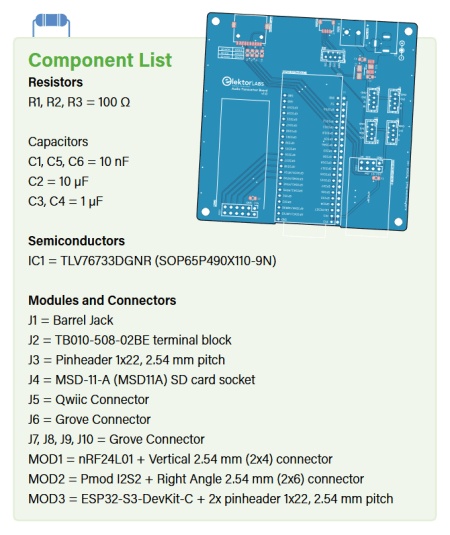
The PCB
The PCB layout is organized around the ESP32-S3-DevKitC (see Figure 6). The connectors are placed on the top side of the PCB, including the power jack, screw terminal, Qwiic connector, and SD card slot. The Pmod connector is located at the lower side of the board to allow compatibility with various Pmod modules. The nRF24 module is positioned on the right edge, and four connectors (J7 to J10) are placed in the middle-right section to provide additional GPIO access for external modules. I2C tracks are short and narrow, suitable for typical communication speeds, and power traces are wider to handle current distribution, with a ground plane covering most of the board.

The Housing
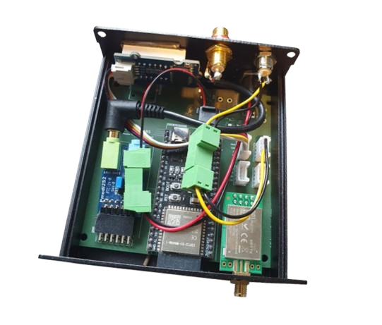
The PCB for the audio transceiver project fits into a 100 × 97 × 40 mm aluminum enclosure with a sliding lid. It mounts directly into the enclosure rails, and the lid makes it easy to access the internals when needed. Metal enclosures are useful for mechanical protection and shielding, but they also block high-frequency signals like Wi-Fi and Bluetooth. The metal acts as a Faraday cage, so wireless communication with the PCB antenna version of the ESP32 DevKit won’t work — unless you provide an opening. For this reason, the ESP32-S3 antenna area is placed at the bottom edge of the board, allowing a small cutout to be made in the enclosure for signal access. If you use an ESP32-S3-DevKit with an antenna connector — for example, the one from the Elektor store — you can mount an external antenna at the front or rear plate of the metal housing.The SMA connector on the nRF24 module is positioned so that a hole can be drilled in the faceplate to mount the antenna externally (see Figure 7).

that a hole can be drilled in the faceplate to mount the antenna externally
— this way, the module remains usable even inside the metal housing.
Demo Software
As said, in the next editions, we will present some applications and further developments. For example, in upcoming “Wireless” edition of Elektor in September 2025, we will present software for transmitting and receiving audio. But we did not want to end this article about the Audio Transceiver Board without some first demo software.
The demo software is a simple WAV audio file player. You can download it from the Labs page for the Audio Transceiver Board. At startup, the ESP32 reads the files that are stored on an SD card (no subdirectories) and puts all the names of the WAV files in a small list. After that, it plays the first audio file from that list. With a press of a button, which is connected to GPIO7 of the ESP32 (at J8), the current track is stopped and the next track comes on turn. Figure 8 shows a prototype with the button. For the prototype, we did not use the SD card socket on the PCB; instead, it is an extra small SD card module, which is connected via SPI to the ESP32. As a connector for the SPI signals, we used the 2x4 “nRF24 socket.”

For the prototype, we did not use the SD card socket on the PCB,
but an extra-small SD card module, which is connected via SPI to the ESP32.
The demo code is modular. Maybe the most interesting software module is Stream_I2S.h, which handles writing the music bytes to the I2S interface. (See the "ESP32 I2S API" section below.) We intentionally did not use one of the powerful big audio libraries — for example, the Arduino Audio Tools by Phil Schatzmann. They can be flexibly used for many hardware platforms, they have a tremendous amount of features, and they are very well documented. On the other hand, they hide the raw music data a bit from the user, and we wanted to show how easy it is to work with the bytes representing the audio signal.
Besides our simple Stream_I2S library, there is a small library SDCardFiles.h, which is based directly on the Arduino standard libraries for SD card access. A very small Button.h lib handles the button presses.
The most important loop of the main program is:
uint8_t bBuffer[128];
...
while (SDCardFiles_DataLeftToRead())
{
SDCardFiles_ReadInBuffer(bBuffer, 128);
I2S_WriteFromBuffer(bBuffer, 128);
...
}
First, we read 128 bytes from the SD card; after that, we write these 128 bytes to the I2S interface of the ESP32. After that, we have enough time to check if a button was pressed or a character was received via the serial interface.
Please consider this software just as a demonstration of how easy it is to work with audio data. Of course, a real player should be completed with a display and better input elements like a rotary encoder.
Espressif I2S API
The ESP32-S3 has two I2S peripheral blocks, which we can use to output and input audio at the same time. On the PCB we have used eight connections for the two interfaces (besides 2x VCC and GND). In general, you can flexibly choose the GPIOs of the ESP32 for the I2S lines.
For outputting and inputting data via I2S, the DMA controller is used, so the processor core is free for other tasks, when the data are transmitted or received. Of course, a DMA buffer is needed. With the ESP32 I2S API provided by Espressif, you can select the number of buffers (at least two) and the number of music samples in each buffer. More on this in one of the next articles.
The API for controlling the I2S interfaces is of course also subject to development. For our purposes, a legacy version [10] fits well, as it is a bit easier to understand than the latest version of the API. A lot of good Arduino audio libraries hide the API commands from the application programmer, in most cases with some wrapper functions (for example [8]). Although these audio libraries are very powerful and flexible, we thought it would be good that you know how the I2S API works. For convenient use, we grouped all commands to start the ESP32 I2S driver in one function (OK, our own wrapper). Here is the code to start the driver for playing audio, you can find it in the file Stream_I2S.h:
// these pin definitions are located in BoardPin.h
#define I2S_MCK_OUT 36
#define I2S_WS_OUT 35
#define I2S_SCK_OUT 48
#define I2S_SD_OUT 47
#define I2S_PORT I2S_NUM_0
uint8_t audiochannelcount = 1;
uint16_t samplerate = 32000;
uint8_t samplebuffer_count = 4;
uint8_t samplebuffer_length = 32;
void I2S_Start()
{
i2s_channel_fmt_t audiochannelformat = I2S_CHANNEL_FMT_ONLY_LEFT;
if (audiochannelcount == 2)
{
audiochannelformat = I2S_CHANNEL_FMT_RIGHT_LEFT;
}
i2s_comm_format_t communicationformat = i2s_comm_format_t(I2S_COMM_FORMAT_I2S | I2S_COMM_FORMAT_I2S_MSB);
i2s_config_t i2s_config_out = {
.mode = i2s_mode_t(I2S_MODE_MASTER | I2S_MODE_TX),
.sample_rate = samplerate,
.bits_per_sample = i2s_bits_per_sample_t(16),
.channel_format = audiochannelformat,
.communication_format = communicationformat,
.intr_alloc_flags = 0,
.dma_buf_count = samplebuffer_count,
.dma_buf_len = samplebuffer_length,
.use_apll = true,
.tx_desc_auto_clear = true, // silence on underflow
.fixed_mclk = samplerate * 256
};
i2s_driver_install(I2S_PORT, &i2s_config_out, 0, NULL);
const i2s_pin_config_t pin_config_out = {
.mck_io_num = I2S_MCK_OUT,
.bck_io_num = I2S_SCK_OUT,
.ws_io_num = I2S_WS_OUT,
.data_out_num = I2S_SD_OUT,
.data_in_num = -1
};
i2s_set_pin(I2S_PORT, &pin_config_out);
i2s_start(I2S_PORT);
}
You don’t have to understand everything in detail for now, but you can see that it is not difficult to change for example the samplerate or the GPIO pins used for the I2S interface.
Here is the API driver command to send 128 bytes of data via the I2S interface to the DAC:
i2s_write(I2S_PORT, &wBuffer, 128, &bytesWritten, portMAX_DELAY);
With this, you'll send 128 bytes of audio to the DAC, which must be located in wBuffer. You can fill it with audio data from the SD card, a generated sine or rectangle audio signal or any other sources. wBuffer can be set up as an array of simple bytes (uint8_t wBuffer[128];) or an array of music samples of 16 bit width, in that case you have to use signed integers (int16_t wBuffer[64];). The i2s_write will work with both sorts of buffers, but the total number of bytes must be 128, as stated in the third parameter of the function.
A quite convenient feature is that i2s_write with portMAX_DELAY as fifth parameter is blocking, until space is available in the DMA buffers. After filling the buffer again, the function returns, and you can do other things, while the data are output without needing the processor. You just have to make sure that you do not waste too much time until calling i2s_write again with the next data packet, before the buffers run empty. That makes it very simple to output data continuously!
For the other way round — sampling data via the ADC — there is a convenient to use i2s_read function:
esp_err_t result = i2s_read(I2S_PORT, &rBuffer, 128, &bytesIn, portMAX_DELAY);
We will use this function in a later article.
Looking Ahead
In the next part of this series about the Audio Transceiver Board project, we will try to send and receive audio data wirelessly. As an appetizer, refer to Figure 7, which shows a prototype of the wireless receiver. Stay tuned!
Editor's Note: This article (250384-01) appears in the Elektor Circuit Special 2025.
Questions About the Audio Transceiver Project?
If you have questions about this article or the audio transceiver project in general, feel free to email the Elektor editorial team at editor@elektor.com.


Discussion (0 comments)