
Arduino-Based LED Cube: Build an Arduino-Based 3D Light Show
on
Here we propose a project that will enchant you with its play of light, even more fascinating in the dark, based precisely on light-emitting diodes; to be exact, a matrix of monochromatic LEDs in three dimensions, arranged in space to form a cube.
This is something striking and at the same time simple, within the reach of even the youngest and those who are getting into electronics for the first time. Add to this the fact that no printed circuit board needs to be built to create it, since the connections of the cube structure are made by soldering the LED terminals together, and the terminal connections to the controller unit can be set up through a matrix prototyping board.
The LED Cube
The structure of the cube consists of four levels (layers) of light-emitting diodes soldered together after bending their leads appropriately and arranging them with the proper polarity. Each level is made up of four rows, which in turn each consist of four LEDs, and a total of 16 LEDs per layer. Thus, the cube consists of 64◦LEDs in total. This is all managed by an Arduino Nano board through connections made using wires that carry the power and are soldered to a holed matrix board. The firmware determines which LEDs in the cube will light up and which will not, creating lighting effects by driving them in multiplex
Our LED cube project then needs the following elements:
- Arduino Nano board;
- 64 LEDs of the preferred color;
- Matrix board to hold the LED structure.
On the Arduino, we’ll upload our custom sketch, which you’ll find on Elettronica In’s Lab page.
The schematic is shown in Figure 1, indicating the connections between the Arduino and LED matrix. The row and column identifier for each LED is in parentheses — for example, (1, 2) means that the specified Arduino pin must connect to the LED at row 1, column 2. This tells you why the number pairs in the diagram are indicated as (Y, X).
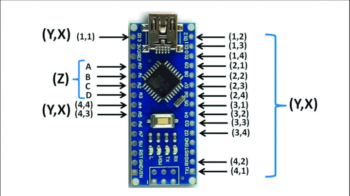
The layers of 16 LEDs each correspond to Z and are to be connected to pins A0 (A), A1 (B), A2 (C), and A3 (D), respectively. The Z designation is more than appropriate because the layers are arranged vertically, thus on the Z axis if you’re looking down, while X and Y are the width and depth of the cube, defined by column.
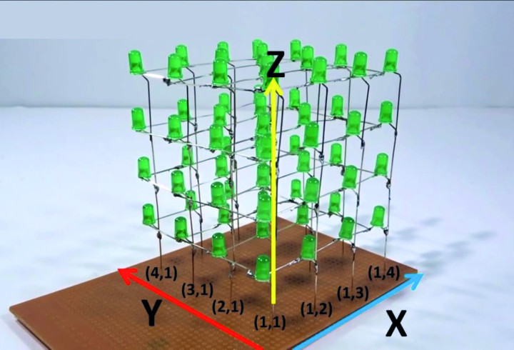
These connections are easier to understand by looking at Figure 2, which shows the spatial arrangement of the LEDs and clarifies the connections of the pairs of numbers shown in Figure 1.
Each connection to the Arduino I/O drives an LED anode, while the cathodes are joined between the diodes of each plane and go to lines A, B, C, and D, which will be cycled to logic low. So, as far as hardware is concerned, each column of our cube is connected to an I/O pin on the board, such that each pin has four LEDs connected to it. But, since our Arduino Nano has only 14 digital pins, we have to use two analog pins as digital pins, achieving 16 digital pins (13, 12, 11, 10, 9, 8, 7, 6, 5, 4, 3, 2, 1, 0, A5, and A4), which will allow us to turn on or off the column we want.
We applied the same procedure to the four levels, to which we connected four pins (A3, A2, A1, and A0): Each pin controls one level, so that by combining the selection (turning on) of a specific level (layer) with the selection of a specific column among the abovementioned 16, we will be able to tell the Arduino which LED to turn on and which to leave off. Using this trick, we’ll be able to realize this project with only 20 I/O pins, which would have been impossible if we had connected an LED to each pin, as we’d have needed 64 pins and — more than our little Arduino can provide.
To summarize, to independently control each LED, we divide the cube into levels (horizontal) and columns (vertical). Each LED placed on the same level (floor) will have the cathode (-) in common with the other LEDs on the same level, while each LED placed in the same column will have the anode (+) in common with the other LEDs in the same column.
In all, there will be four pins to control to select the level to be powered and 16 anodes that power the individual columns. When we need to turn on a particular LED we will have to make sure that its level is brought to logic zero and that the column to which it belongs is active, that is, brought to logic one.
Practical Realization
Well, having come to this point, we can explain how to make our LED cube. Besides the 64 light-emitting diodes (in our case, round LEDs with a diameter of 5 mm were adopted) and the Arduino Nano, you will need some 0.5 ~ 0.8 mm2 rigid copper wire and flexible cable for the connections to the cube and between the LEDs that make it up.
We also recommend that you use a square of cardboard (or of faesite or masonite of small thickness, such as 3 mm) measuring 13×13 cm, which will serve as a matrix or template, which you’ll need to build the levels of your cube. Basically, you mark this cardboard with four vertical lines and as many horizontal lines, then make four equidistant dots for each line so that you end up with 16 dots, each the same distance apart from the next.
You will then pierce the cardboard with the tip of the pen, just enough to fit one LED upside down, resulting in something that looks like Figure 3; then to make the planes that will then form the cube, each of which is composed of 16 LEDs (in a 4×4 matrix) that will also be arranged equidistant from each other, pierce the cardboard at the intersections between the rows to maintain the correct distance within the structure.
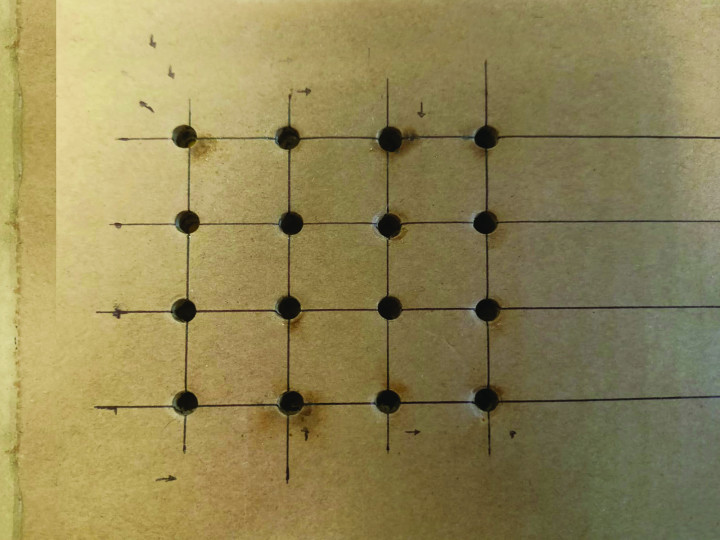
In our case, the distance (spacing) between each LED and the one next to it is 3 cm — a distance that, we feel, is the optimum to achieve a compact and functional display of the figures formed by the cube in the dark.
So, take the square of perforated cardboard and insert as many LEDs into the 16 holes, upside down (i.e., with the “head” in the holes), at which point you can bend the terminals and start soldering the component ones together in a plane; this template not only allows you to set a precise distance between the LEDs, but also to hold the light-emitting diodes in place to facilitate soldering. Then bend the cathodes at right angles and tin them together: For this purpose, bend them so that the one from one LED can touch the one from the next and be tinned to it. If the terminals are not long enough, connect the cathodes of each line with a piece of stiff copper wire and then, crosswise, join the lines of each plane with the usual wire until a grid is made. Instead, the anodes should be bent at a step, that is, once at a right angle and then again at another right angle about 3 mm away, just enough so that they can pass to the side of the heads of the LEDs below. Then, they must be joined (if their length is not sufficient, with stiff copper wire) to those in the next layer.
When you have completed one level, take it out of the cardboard template and wire another similarly. Once you have reproduced these planes in the same way, you will have to connect them vertically, through the anodes, to create a sort of cage that will support the structure, making it strong and allowing it to acquire a cube-like shape. The vertical connection will have to be one for each column of LEDs and one for each of the 16 LEDs on each level. In fact, there are 16 columns in all (the first LED on each level will have to match the one on the level below, and so on).
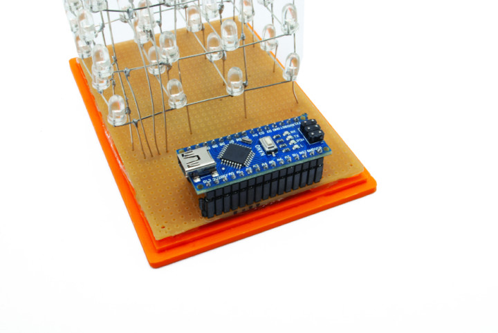
To assemble the whole thing and connect it, it is advisable to use matrix board of the appropriate size — at least 10×10 cm. In its holes, insert the ends of the columns of the cube, 16 in all, tinning them in the corresponding pads, then connect them with pieces of copper wire in insulation, to the pins of the Arduino Nano board according to what has already been explained, and referring to the indications in Figure 1 and Figure 2. A more detailed view of the assembly and connections is offered in the wiring diagram of Figure 4.
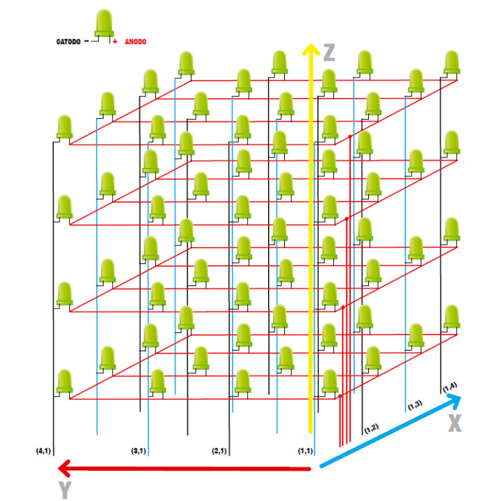
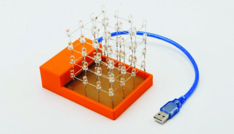
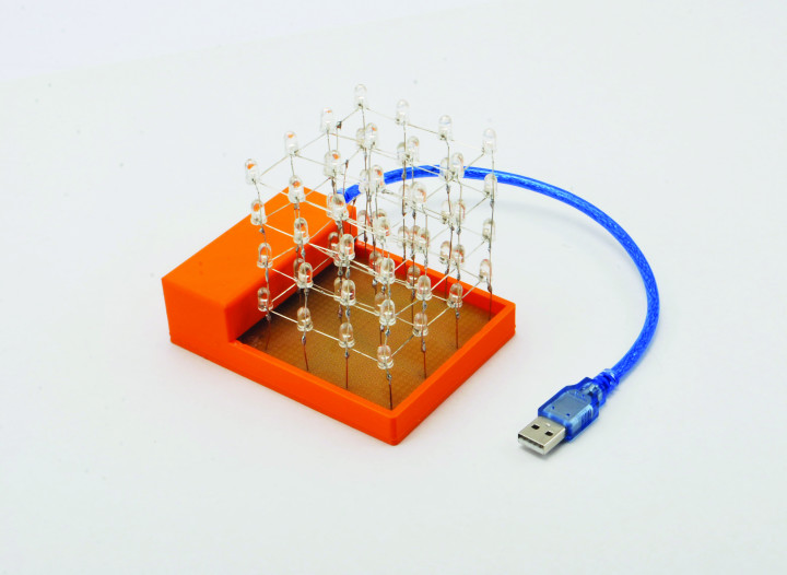
When the work is completed, you will get something like that shown in the prototype photos in this article. As you’ll see, high-brightness diodes in a transparent package have been used; if you wish to have a more uniform, albeit less intense, light emission, you can use conventional LEDs (which typically emit at an angle of 120 ÷ 140 degrees) with the colored casing: for example, the green ones proposed in Figure 2, again 5 mm in diameter.
Mind that the entire circuit works with power drawn from the micro-USB connection of the Arduino Nano board, which you will connect to a computer or, once the sketch is loaded, to a power supply with a Micro-USB connection, capable of delivering at least 500 milliamperes.
Firmware
The code we came up with is based on the principle of operation already stated: The Arduino must control four pins that will be used to select the layer to be powered and 16 anodes that will power the individual columns. When we need to turn on a given LED of the three-dimensional matrix that makes up the cube, we will have to make sure that its layer (i.e., the one on which it is physically and electrically…) is powered (i.e., that its cathodes are grounded from the Arduino Nano line between A, B, C, and D) and that its column is active; by doing so, we will turn on one LED at a time for each level.
The first thing we did was set up the pins (basically, in the listing, we wrote down the I/O pins that we need for this project). Setting the pins up within the code is used to configure a particular pin on the Arduino and determine whether it should be an INPUT or OUTPUT line.
In this case, the declared pins have been divided into column[] and layer[] arrays, which are active outputs at logic high and logic zero, respectively (Listing 1).
4x4x4 LED Cube
Connection Setup:
Columns
[(x,y)-Pin]
(1,1)-13
(1,2)-12
(1,3)-11
(1,4)-10
(2,1)-9
(2,2)-8
(2,3)-7
(2,4)-6
(3,1)-5
(3-2)-4
(3-3)-3
(3,4)-2
(4,1)-1
(4,2)-0
(4,3)-A5
(4,4)-A4
Layers
[layer-Pin]
a-A0
b-A1
c-A2
d-A3
*/
//initializing and declaring led columns
int column[16]={13,12,11,10,9,8,7,6,5,4,3,2,1,0,A5,A4};
//initializing and declaring led layers
int layer[4]={A3,A2,A1,A0};
int time = 250;
Then follows the setup() function, in which the firmware settings are defined, and the for loop, which is the basis for the display of the light effects, because it defines the alternation of logic levels on the pins of the Arduino board, to controlling the LEDs in multiplex. Finally, we move on to the loop(), which contains all the routines relevant to the intended light shows (refer to Listing 2).
{
Serial.println(“sono nel loop”);
turnEverythingOff();//turn all off
flickerOn();
turnEverythingOn();//turn all on
delay(time);
turnOnAndOffAllByLayerUpAndDownNotTimed();
layerstompUpAndDown();
turnOnAndOffAllByColumnSideways();
delay(time);
aroundEdgeDown();
turnEverythingOff();
randomflicker();
randomRain();
diagonalRectangle();
goThroughAllLedsOneAtATime();
propeller();
spiralInAndOut();
flickerOff();
turnEverythingOff();
delay(2000);
}
Within this loop are calls to the individual functions corresponding to the light shows, which we show in Listing 3: the propeller light animation, the visual effect of which is to turn on the LEDs of the levels in sequence so that a rotating light looks like the movement of a propeller.
void propeller()
{
turnEverythingOff();
int x = 90;
for(int y = 4; y>0; y--)
{
for(int i = 0; i<6; i++)
{
//turn on layer
digitalWrite(layer[y-1], 1);
//a1
turnColumnsOff();
digitalWrite(column[0], 0);
digitalWrite(column[5], 0);
digitalWrite(column[10], 0);
digitalWrite(column[15], 0);
delay(x);
//b1
turnColumnsOff();
digitalWrite(column[4], 0);
digitalWrite(column[5], 0);
digitalWrite(column[10], 0);
digitalWrite(column[11], 0);
delay(x);
//c1
turnColumnsOff();
digitalWrite(column[6], 0);
digitalWrite(column[7], 0);
digitalWrite(column[8], 0);
digitalWrite(column[9], 0);
delay(x);
//d1
turnColumnsOff();
digitalWrite(column[3], 0);
digitalWrite(column[6], 0);
digitalWrite(column[9], 0);
digitalWrite(column[12], 0);
delay(x);
//d2
turnColumnsOff();
digitalWrite(column[2], 0);
digitalWrite(column[6], 0);
digitalWrite(column[9], 0);
digitalWrite(column[13], 0);
delay(x);
//d3
turnColumnsOff();
digitalWrite(column[1], 0);
digitalWrite(column[5], 0);
digitalWrite(column[10], 0);
digitalWrite(column[14], 0);
delay(x);
}
}
//d4
turnColumnsOff();
digitalWrite(column[0], 0);
digitalWrite(column[5], 0);
digitalWrite(column[10], 0);
digitalWrite(column[15], 0);
delay(x);
}
Of course, to install the sketch in Arduino, you have to connect the Arduino◦Nano board (whether it is mounted in the cube circuit is irrelevant…) then start the IDE, then from the Tools → Board menu, choose the Arduino Nano board and then open (File → Open) the sketch, and then start loading it into the Arduino by clicking the Load button.
Adapting it to Your Own Needs
The advantage of this LED cube project is that you’re able to configure it to your liking, adding new lighting effects, although, to achieve this, you need to have some knowledge of Arduino C programming. However, don’t worry too much, because even just by searching here and there on the internet, you’ll find many similar projects to control LEDs, and even beyond, with the corresponding hardware complexities.
To configure the sketch to control more light-emitting diodes, you will only need to copy and paste the code onto the board program (for the inexperienced), then you will only need to change the array initialization within the code or change the connections of the levels and columns on the Arduino. That being said, all that remains is for us to wish you good luck and lots of fun with your light cube!
Editor's notes: This project originally appeared in Elettronica IN.

Discussion (1 comment)