
Moisture Sensors for Watering Systems
on

Before you start working with moisture sensors, consider the following tips about sensor selection and sensor integration. Once you are familiar with the basics, you can begin integrating the sensors using the Arduino IDE for boards such as Arduino and ESP.
For many years, I have been using automatic watering systems to make gardening more convenient. My first system consisted of a simple timer clock with inexpensive solenoid valves, like the ones used in washing machines. The next generation featured an Arduino board with a display, and it obtained its information from simple capacitive moisture sensors, and even maintained a watering log. My current watering system is based on an ESP32 and is fully integrated into my home automation system. This allows me to manually switch on the watering system, view the most recent watering times, set these times and other parameters, and much more. I hope you can benefit from my experience.
The above description is not entirely complete. For instance, there is also an alarm function that reports things like when a watering session failed, for example due to a broken hose. The system can also be operated from a web browser, and the software can be updated over the air.
The watering system is, however, not the focus of this article because it is very much designed to meet my specific needs. Instead, I would like to describe my experience in selecting moisture sensors, since I have learned a lot about them over the years.
Moisture sensors have two tasks in a watering system: they inform the system about the current watering status, and as a result they help to make economical use of water as a resource. Quite a few plants are equally intolerant to waterlogged and dry soil. Although there are an enormous number of moisture sensors, it appears that only a few really work properly.
After a brief overview of the operating principles of the most common moisture sensors, this article focuses on sensor integration using the Arduino IDE for commonly used boards such as Arduino or ESP. If you are currently using a watering system without sensors or are not satisfied with your moisture sensors, you’re in the right place here.
Measuring Soil Moisture
There are a number of different definitions of soil moisture. The volumetric water content, which means the proportion of water in the total volume of soil, is usually what is wanted. If all air spaces in the soil are filled with water, the maximum volumetric water content in natural soil is approximately 50 to 60%. Higher values are possible in peat and other organic materials.
The gravimetric water content relates to the relative mass of water in the soil and can be determined, for example, by weighing a soil sample before and after drying. This parameter must be measured in a lab, so it is not suitable for the continuous monitoring of soil moisture.
Electrical soil moisture sensors are based on a variety of physical measurement principles. Measuring the electrical conductivity is very inexpensive, but unfortunately not reliable because the conductivity is also dependent on the amount of dissolved ions. With the same water content, measuring the conductivity can lead to completely different results depending on the type of soil, salt content and fertilisers. The conductivity is also strongly temperature dependent, and compensating for this is virtually impossible in practice. However, the biggest problem is corrosion of the sensor electrodes, which often last only a few days or weeks.
Capacitive sensors with electrodes protected by an insulating layer are much better in this regard. The measurement principle is based on the interaction of water molecules with an electric field, since water molecules are dipoles with positive and negative ends. If a dipole is placed between the electrodes of a plate capacitor and a voltage is applied to the metallic electrodes, the dipole will align itself to the electric field (see Figure 1).
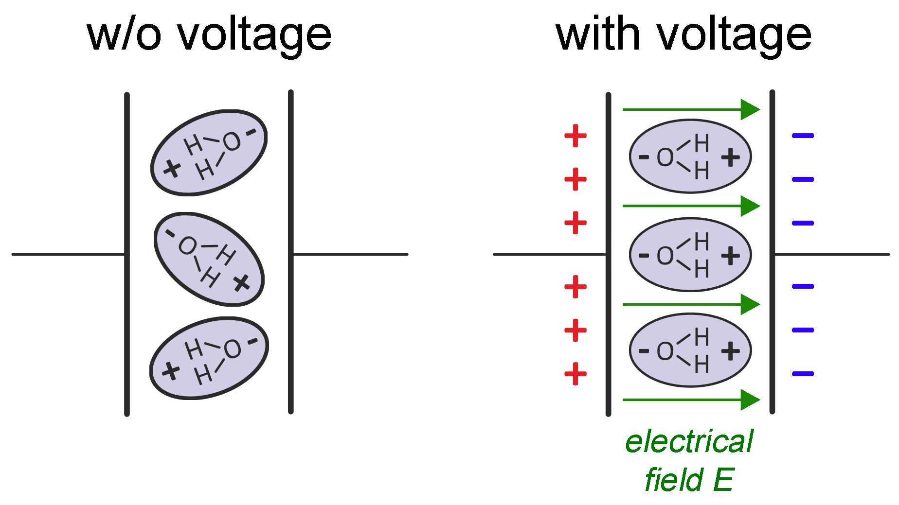
This polarisation effect is expressed by the dielectric constant εr. It ranges from εr = 1 for air through εr = 3 to 8 for mineral soil particles to εr = 80 for water. The effective dielectric constant of a given soil, consisting of a mix of air, water and soil particles, is therefore largely determined by the water content. If a soil sample is placed between the electrodes of a capacitor and the resulting capacitance is measured, the associated dielectric constant can be calculated and from it the water content. In practice, an AC voltage is applied to the electrodes to reduce electrolysis at the capacitor electrodes, disturbances from surface polarisation, and the influence of soil conductivity. Increasing the frequency of the measurement signal leads to more accurate results and increases the immunity to interference. Frequencies above 100 MHz are ideal, but would make the circuitry significantly more expensive.
Conductivity Sensors
Measuring principle: The soil moisture is determined by measuring the electrical conductivity of the soil between two electrodes. The sensor is usually supplied with an analog signal processing circuit with an adjustable threshold value (see Figure 2).
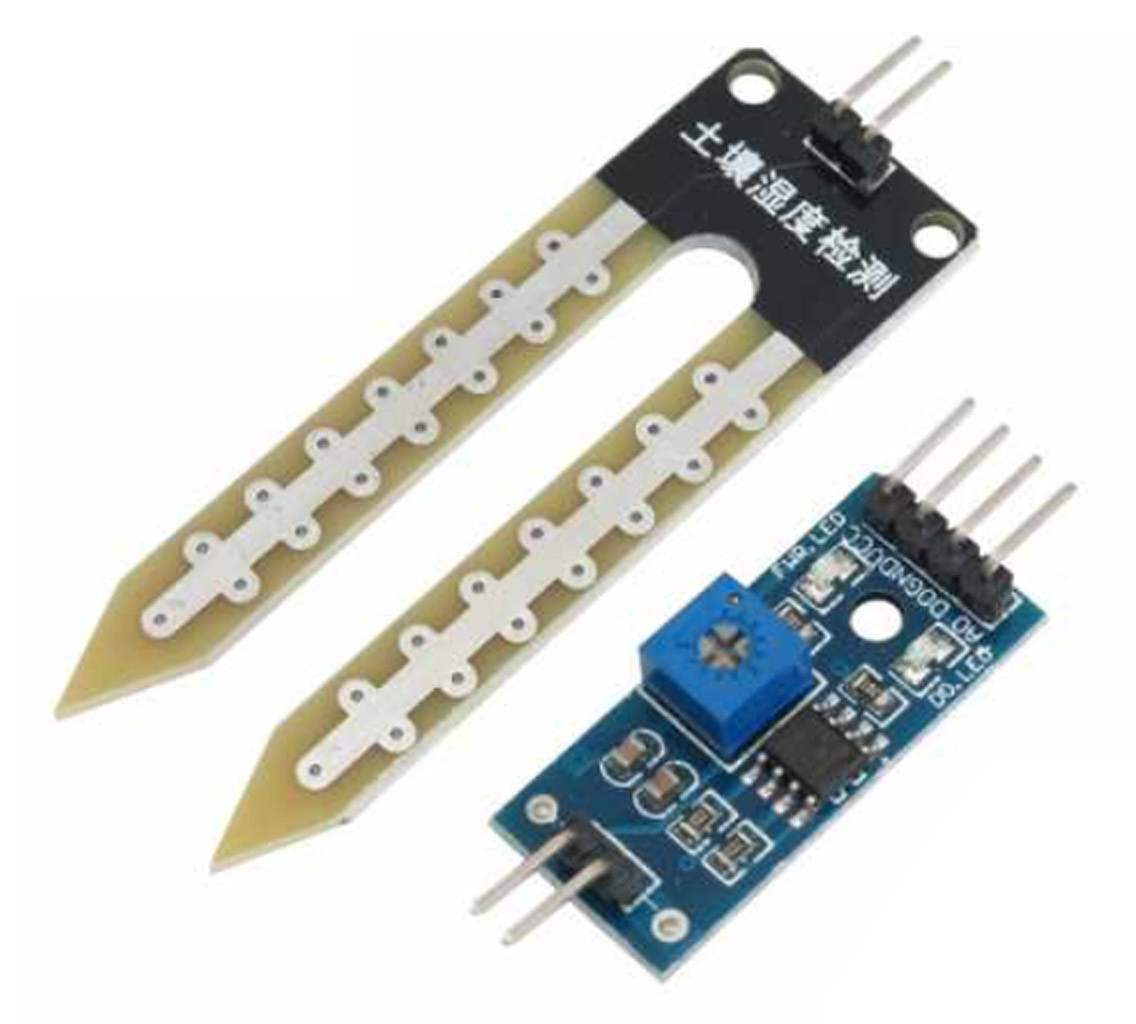
Disadvantages: The electrical conductivity of soil depends not only on the water content, but also strongly on the salt content, fertilisers and soil type, and is therefore an unreliable measure of soil moisture. The sensor is exposed to strong corrosion in the soil and consequently has a short lifetime. This also applies to electrodes with thin gold plating. In addition, the terminals are usually not protected against water.
Advantage: Very economical.
Low-Frequency Capacitive Sensors
Measuring principle: The soil moisture is determined by measuring the capacitance. The electronic circuit operates at low frequencies in the range of several kilohertz to around 1 MHz. Many different versions can be found online, often working with an NE555 timer (see Figure 3).
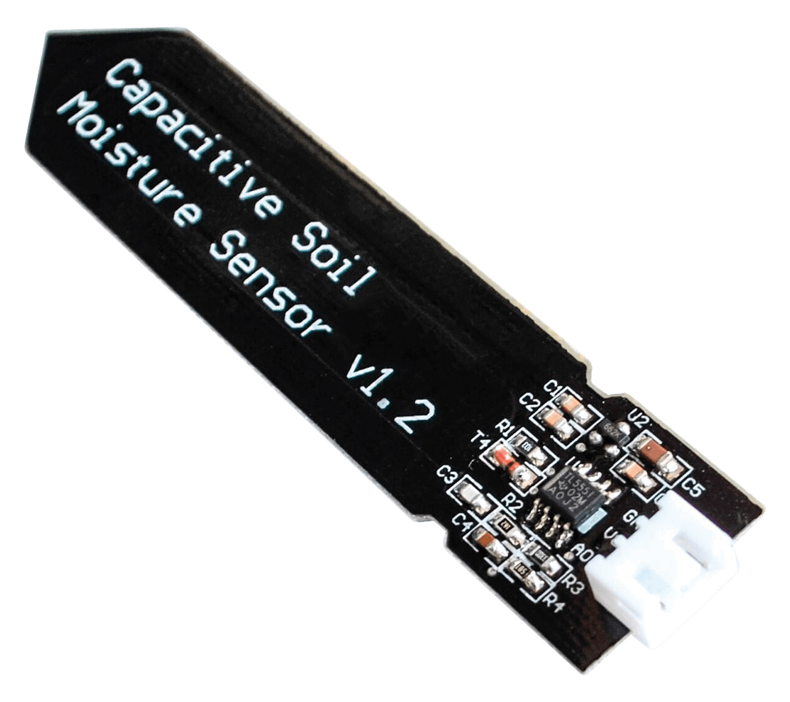
Disadvantages: Due to the low operating frequency, moisture measurements are more strongly influenced by other factors such as the electrical conductivity and temperature of the soil, so only limited accuracy is possible. The electrodes are often only protected by a thin layer of solder resist, which does not last long in the soil. The circuit and terminals are often not sealed water-tight. Advantage: Fairly economical.
VH400 High-Frequency Capacitive Sensor
Measuring principle: The soil moisture is determined by measuring the capacitance. Disadvantages: Medium price range. The influence of the soil type on the measurement is still noticeable. The electrodes are very close together, so the electrical measurement field barely extends beyond the circuit board and the suitability of the sensor for large-grained soil is limited (see Figure 4). The measurements are temperature dependent and change when the connecting cable is touched with the hand.
Advantage: Sufficiently accurate moisture measurement in many types of soil.
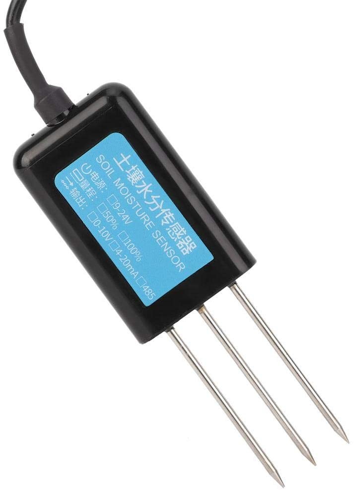
CWT-SOIL-H-S
Measuring principle: No information available regarding the measuring principle or measuring frequency. Disadvantage: Medium price range. Frequent failures after a short time in the soil. Advantages: Holds the promise of additional measurement of electrical conductivity; various versions (see Figure 5).
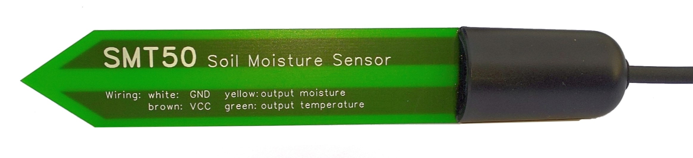
SMT 50 High-Frequency Capacitive Sensor
Measuring principle: The soil moisture is determined using a capacitive voltage divider. The circuit operates at 16 MHz or above. Disadvantages: Medium price range. The influence of the soil type on the measurement is still noticeable. Advantages: The measuring frequency is high enough for reliable moisture measurement in many types of soil. The electrodes are embedded in a multilayer circuit board, providing good mechanical protection and long lifetime in the ground. The circuitry is encapsulated in epoxy to make it completely waterproof (see Figure 6). The 10 m long connecting cable with a polyurethane sheath is suitable for underground installation (resistant to microbes and hydrolysis).
DAV-6440 Tensiometer
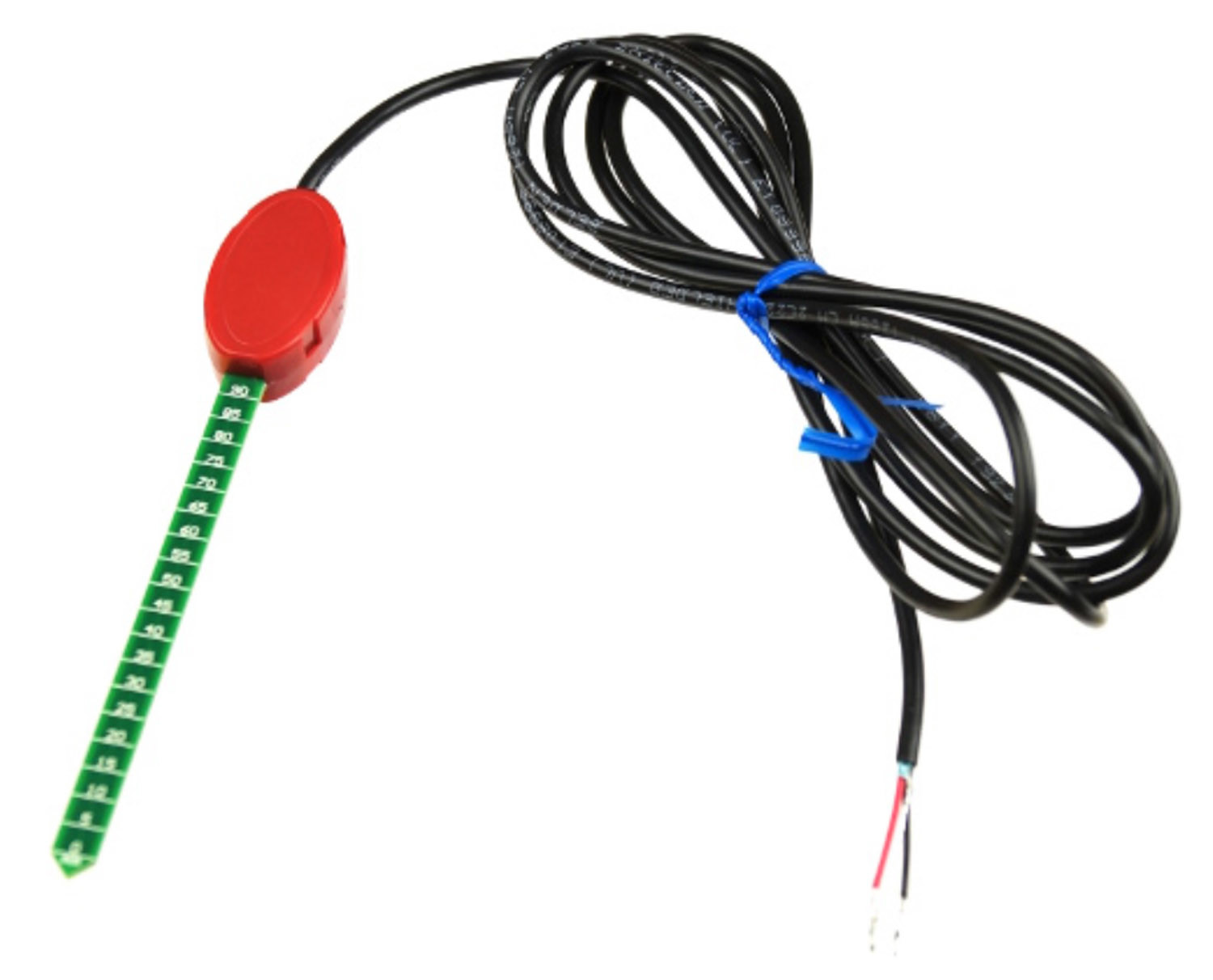
Measuring principle: This Watermark sensor is an example of a tensiometer, which measures the soil moisture tension (correlated to the water content of the soil). For this the electrical resistance of a material in hydraulic contact with the soil is determined (see Figure 7). Other tensiometric sensors use a non-woven fabric in contact with the soil and determine its water content by electrical heating while observing the temperature (e.g. Gardena sensors).
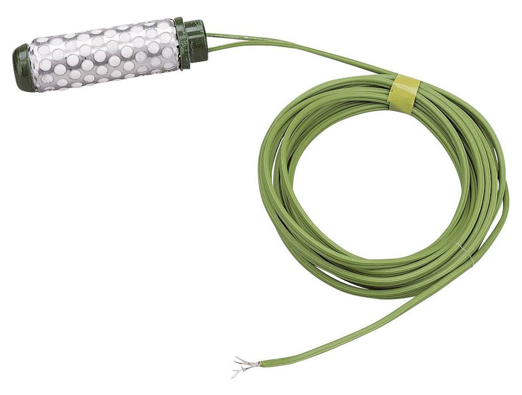
Disadvantages: Tensiometers are sluggish and respond slowly to changing soil moisture. There is a hysteresis effect, resulting in different measurements with the same soil moisture tension (with rising versus falling water content). Under very dry conditions the sensor can lose hydraulic contact with the soil. The stated lifetime of this sensor in the ground is at least 5 years, which is not especially long. Advantage: The soil moisture tension indicates the soil moisture available to the plants.
SMT 100 TDT Sensor
Measuring principle: This time domain transmission (TDT) sensor consists of conductor loops forming a high-frequency transmission line that is driven by pulse signals (see Figures 8 and 9).
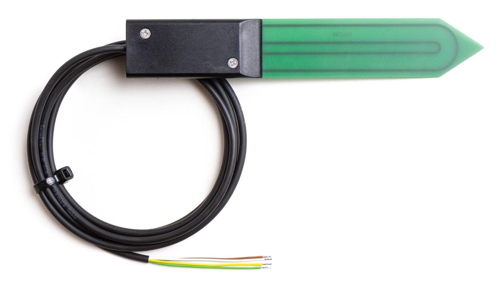
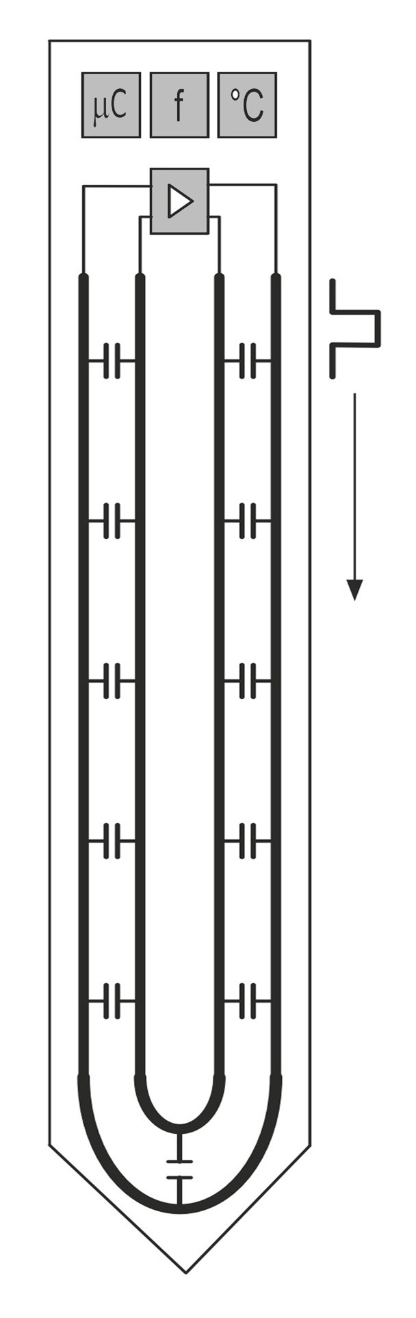
A ring oscillator is implemented by feedback to an amplifier, and its frequency is measured by a microcontroller. The capacitance between the electrodes is influenced by the soil moisture. The higher the moisture content, the longer the pulse propagation time and the lower the frequency of the ring oscillator. Disadvantage: Upper price range. Advantages: The measuring frequency is over 150 MHz, enabling high accuracy with good resolution combined with minimal influence of the soil type on the measurement. Thanks to a multilayer circuit board with epoxy encapsulation and a high-grade cable, the sensor achieve a long lifetime in the soil. A large selection of interfaces is available, including analog output, RS-485 (TBUS/ASCII and Modbus), SDI-12 and 4-20 mA current loop. The SMT 100 sensor is often used for professional purposes (precision agriculture or scientific applications in hydrology and soil science).
Integration of Sensors in Watering Systems
As previously mentioned, low-cost sensors have analog interfaces and only higher-grade sensors have digital interfaces. Simple analog sensors can be integrated easily in the Arduino IDE without additional libraries. All you need is an analog input. Pin A0 of an Arduino Uno is used in the following example program.
int SENSOR_PIN = A0; /* select analog pin */
int SENSOR_VAL = 0; /* variable storing sensor value */
void setup()
{
Serial.begin(9600); /* setup serial connection */
}
void loop()
{
/* read value */
SENSOR_VAL = analogRead(SENSOR_PIN);
Serial.println(SENSOR_VAL); /* output value */
}
Higher-grade sensors, such as the CWT-SOIL-H-S or SMT 100, provide digital interfaces. In my system both sensors are connected through a Modbus RS-485 interface. The advantages of this connection are obvious: Long cable runs (up to 100 m from the sensor to the control unit) are not a problem, and data transmission is immune to interference. In addition, many sensors can be connected over the same interface.
The CWT-SOIL-H-S sensor basically works well, but in my system two sensors simply stopped working after two years or started indicating unrealistic values. In addition, the included user guide is understandable but the configuration tool described in the user guide is difficult to find online and is only in Chinese. For this reason, only the integration of the SMT 100 sensor is discussed below.
First some remarks about RS-485 and Modbus. RS-485 is a differential serial interface with two lines that transmits data in differential mode, which suppresses common-mode interference and improves the signal-to-noise ratio compared to RS-232. Robust connections up to 100 m long can be made with simple unshielded twisted-pair cables. Modbus is a client/server communication protocol, developed in 1979 for communication with programmable logic controllers. This open protocol has become an accepted industry standard. All technical documents are freely available here. Each node basically has a unique address for accessing the node.
Configuring Sensors
For initial experiments with the SMT 100, it is advisable to use a USB/RS-485 bridge or a PCIe RS-485 card so that the sensor can communicate directly with a laptop or desktop computer. I use a well-documented USB adapter based on an FTDI IC.
A very convenient Modbus configuration program can be downloaded from the website of the sensor manufacturer. After unpacking and installation, proceed as follows to connect the RS-485 version of the sensor to the RS-485 interface: The white wire of the sensor cable is ground, the green wire is RS-485 A, and the yellow wire is RS-485 B. A supply voltage in the range of +4 V to +24 V (with respect to ground) must also be connected to the brown wire.
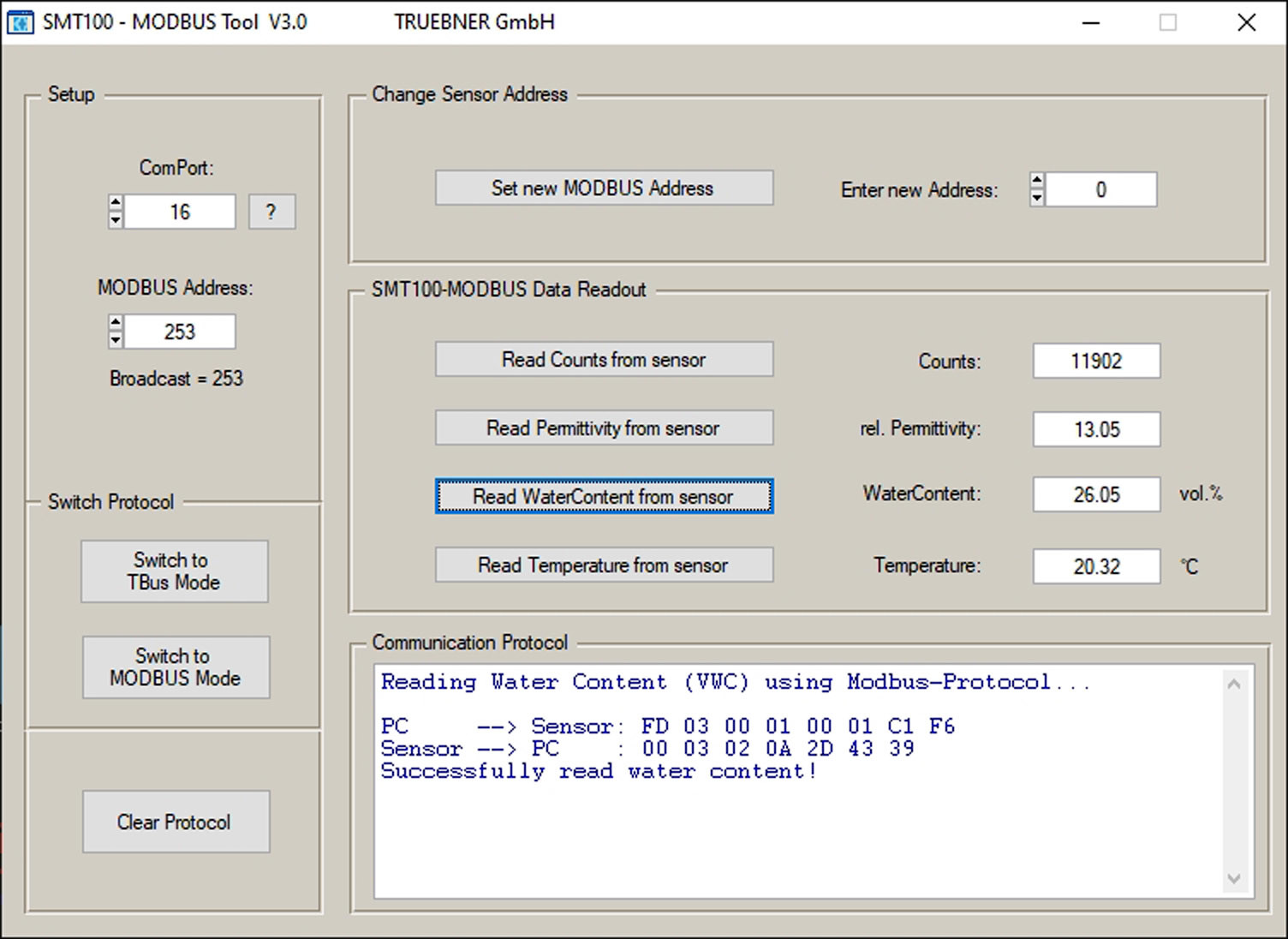
After launching the Modbus tool, you first have to select the COM port. If you are using a USB adapter and no port is shown, you need to install the appropriate driver. If everything is okay, the window shown in Figure 10 appears.
Now you can read out the individual parameters or change the Modbus address. By default the sensor is accessible at address 253 (Broadcast). If you want to connect multiple sensors, each sensor must have a unique address. In the example program the Modbus address is set to 1 by the instruction Set new MODBUS Address. To be on the safe side, you can check communication via address 1, for which Modbus Address on the left must be set to 1. Note that only one sensor at a time can be connected to the bus when setting the address.
A Test Program
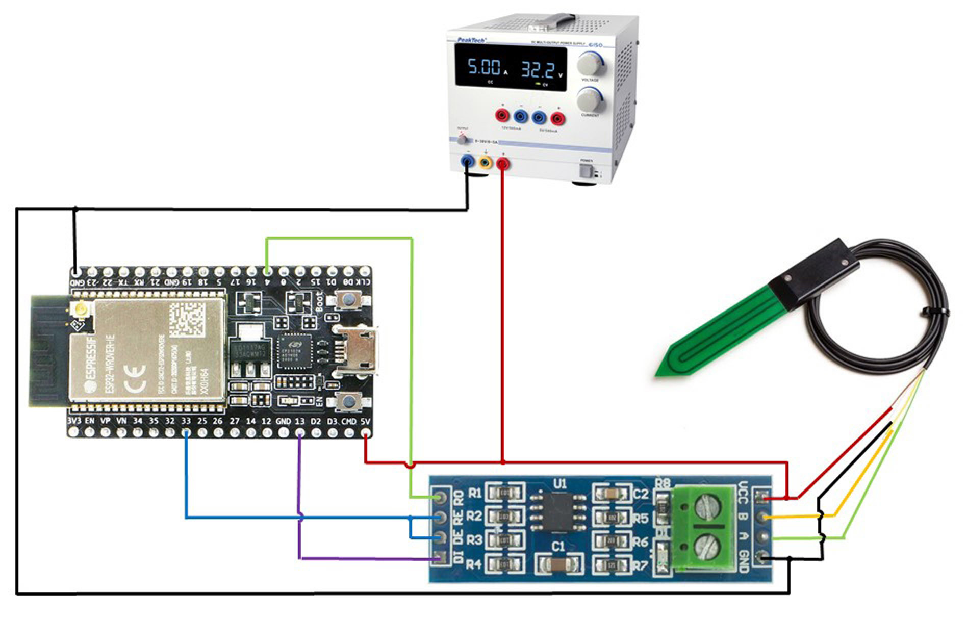
Now let’s see how this sort of sensor can be integrated into a watering system. The test setup is shown in Figure 11.
Along with the readily available ESP32-DEV-Kit, it consists of a small board that converts the RS-485 signal from the sensor into TTL levels suitable for the microcontroller. Terminal DI is an input for serial data transmission from the ESP32 to the sensor. Terminal RO receives data from the ESP32 to be sent to the sensor. Terminals DE and RE are connected together here. When these terminals are pulled low, the receiver in the MAX485 IC is enabled, and when they are pulled high the MAX485 transmitter is enabled.
Now let’s look at the test program. The first part (before the setup routine) defines the pins and the variables for the sensors. In the setup routine the pin for switching the transmitter/receiver is initialised, the standard serial interface is defined as the debug interface, the serial interface to the sensor is initialised as ‘Hardware Serial Interface 2’, and a subroutine checks whether the sensor is connected properly.
In the main loop the sensor is polled every three seconds by calling the subroutine SUB_RECEIVE_HUMIDITY, and the result is output. Querying the sensor values is handled by three subroutines: SUB_CHECK_HUMIDITY checks the received sensor address for correctness to verify that a sensor is connected, SUB_RECEIVE_HUMIDITY fetches the sensor value, and SUB_CALCULATE_CRC calculates the CRC checksum. The complete, extensively commented example code can be downloaded free of charge. If the output in the Arduino Serial Monitor window is similar to that in Figure 12, everything is working right.
Watering Strategy
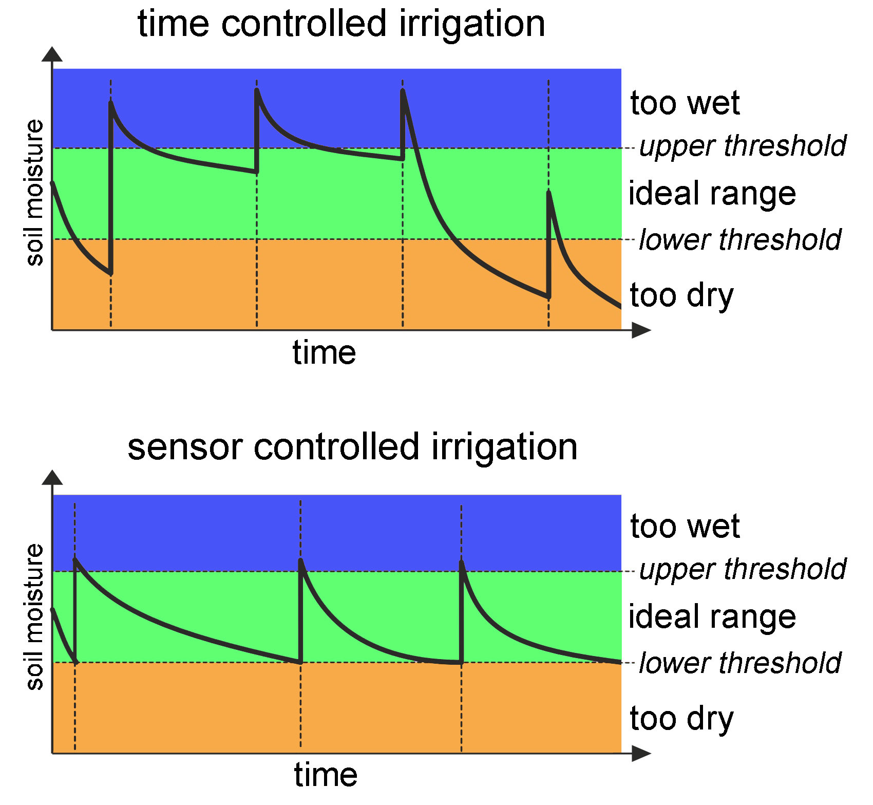
Conventional time-controlled watering irrigates in fixed time intervals, regardless of the actual need for watering. It can therefore lead to overwatering with harmful waterlogging or to underwatering and dry stress, depending on weather conditions. This can be mitigated by using a rain sensor or online weather information. Sensor-controlled watering is much better. This not only allows optimal water supply to the plants, but also reduces water consumption. The differences are shown in the chart in Figure 10. There are various strategies for setting the threshold levels. An experienced gardener can recognise the start of dry stress by observing the plants (slight wilting, rolling of leaf edges). Excessive watering results in saturation, with no further increase in soil moisture. If you wait a while (around 24 hours), the excess water will drain into the subsoil. As a rule of thumb, you can set the lower threshold to 60% of the saturation level. During the learning phase, observe the plants together with the moisture trend and adjust the threshold levels as necessary to achieve long-term optimal and economical automatic watering. It is important to position the sensor properly in the root area of the plants. To obtain a good soil moisture cycle with drip irrigation, the sensor should not be placed too far away or too close to the drip location.
Questions or Comments?
Do you have any questions or comments about this article? Contact the author at peter.tschulik@chello.at or the Elektor editorial team by email at editor@elektor.com.
Discussion (0 comments)