
Multitasking with Raspberry Pi
on
Multitasking has become one of the most important topics in microcontroller-based systems — namely, in automation applications. As the complexity of the projects grows, more functionality is demanded from the projects and such projects require the use of several inter-related tasks running on the same system and sharing the CPU (or multiple CPUs) to implement the required operations. As a result of this, the importance of multitasking operation in microcontroller-based applications has been steadily growing over the last few years. Many complex automation projects nowadays make use of some form of a multitasking kernel. In the book, Multitasking with Raspberry Pi (Dogan Ibrahim, Elektor, 2020), the Python 3 programming language is used with the Raspberry Pi 4. Other models of Raspberry Pi can also be used without any change to the code.
The book is project-based. Its main aim is to teach the basic features of multitasking using Python on Raspberry Pi. Many fully tested projects are given in the book using the multitasking modules of Python. Each project is fully described and discussed in detail. Complete program listings are provided for each project. Readers should be able to use the projects as they are, or modify them to suit their own needs.
Showcase: a traffic lights controller
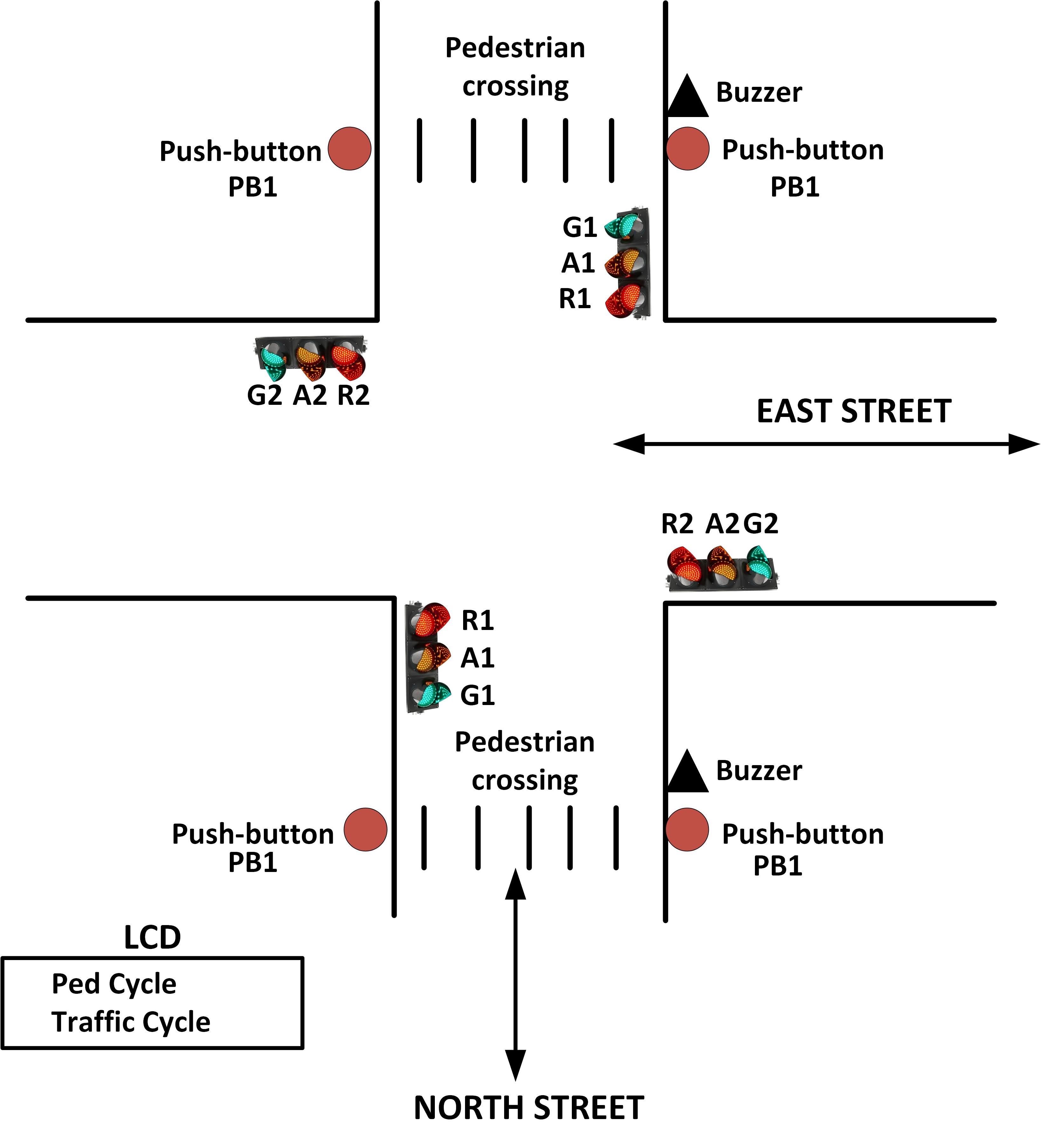
In this project, a simple traffic light controller is designed for a junction. The junction is located at the intersection of two roads: East Street and North Street. There are traffic lights at each end of the junction. There are pedestrian buttons located near the traffic lights on North Street. Pressing a pedestrian button turns all lights to red at the end of their cycles. A buzzer is then sounded to indicate that the pedestrians can cross the road safely. Also, an LCD is connected to the system to display whether the pedestrian cycle is running or the traffic cycle is running. Figure 9.12 shows the layout of the equipment at the junction.
In this project, the following fixed times are given to each traffic light duration, and also to the duration of the pedestrian buzzer. For simplicity, both roads of the junction are assumed to have the same timings:
- Red time: 19 seconds
- Amber time: 2 seconds
- Green time: 15 seconds
- Amber+Red time: 2 seconds
- Pedestrian time: 10 seconds
The total cycle time of the lights in this example project is set to be 38 seconds.
The sequence of traffic lights is assumed to be as follows (different countries may have different sequences):
- Red Amber+Red Green Amber ...
- Green Amber Red Amber+Red ...
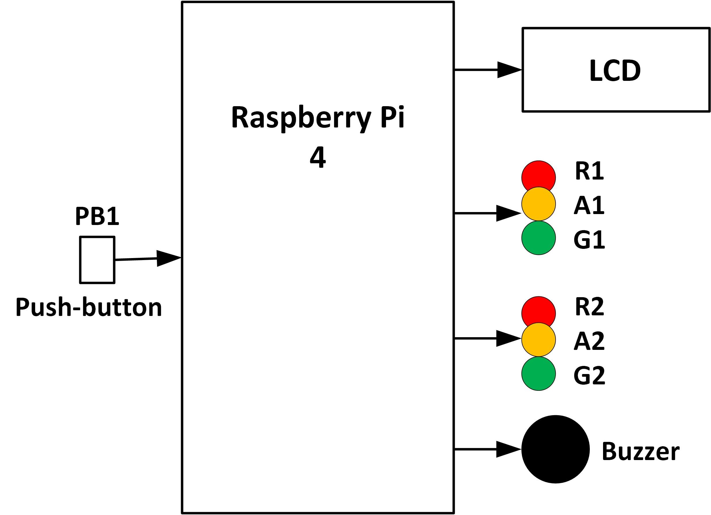
Figure 9.13 shows the block diagram of the project.
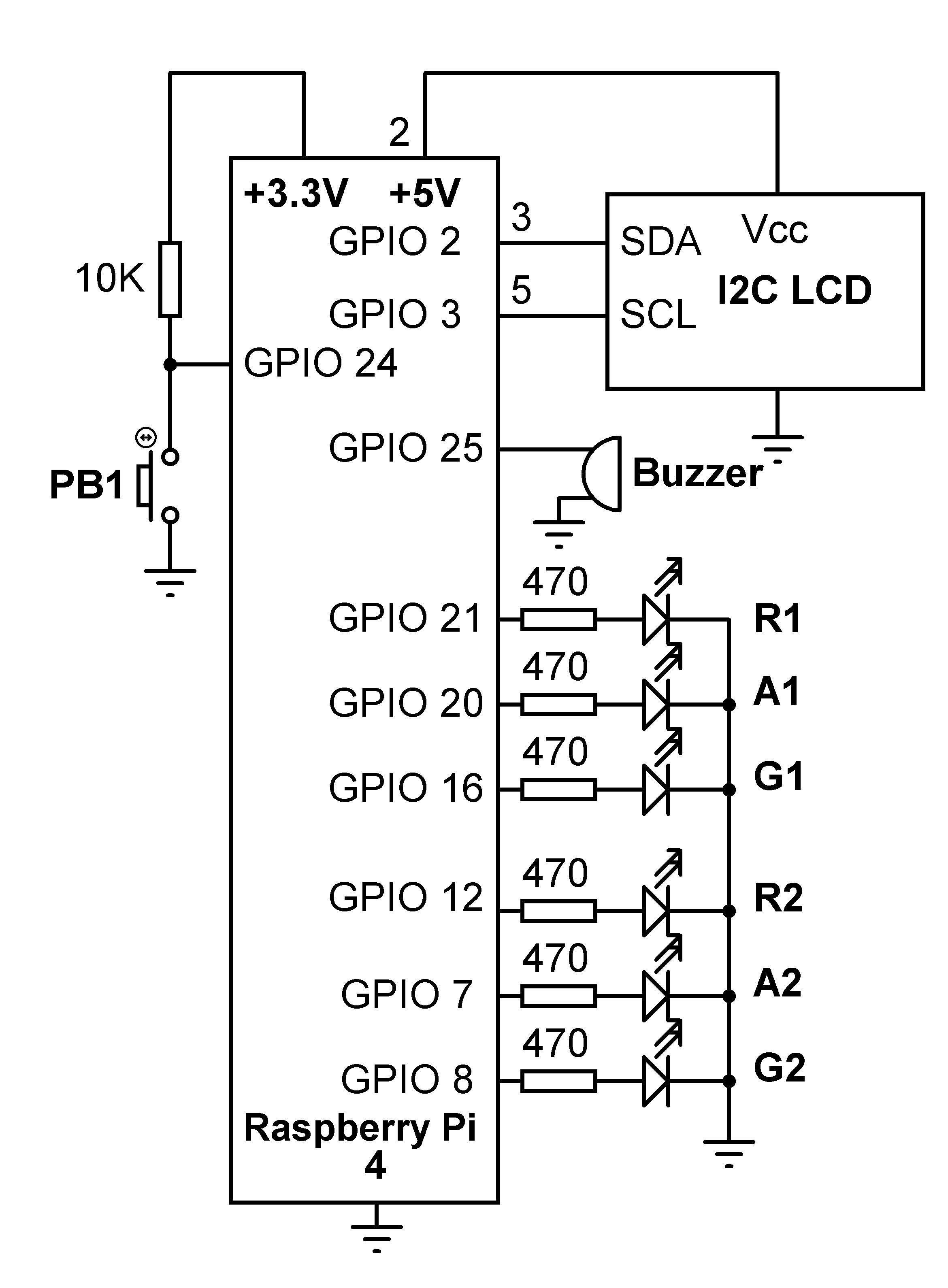
The circuit diagram of the project is shown in Figure 9.14. Red (R), Amber (A), and Green (G) LEDs are used in this project to represent the real traffic lights.
The following connections are made between the Raspberry Pi and road traffic equipment:
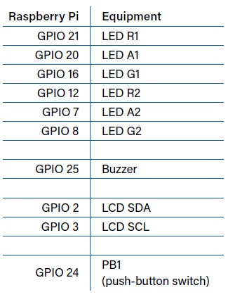
Figure 9.15 shows the full program listing (program name: traffic.py; download). At the beginning of the program the modules called RPi, time, I2C LCD driver, and multiprocessing are imported to the program and two queues named pedq and lcdq are created.
#--------------------------------------------------------------------
# TRAFFIC LIGHTS CONTROLLER
# =========================
#
# This is a traffic lights controller project controlling lights
# at a junction. 6 LEDS are used to represent the traffic lights.
# Additionally a button is used for pedestrian crossing, and an
# LCD shows the state of the traffic lights at any time
#
# Author: Dogan Ibrahim
# File : traffic.py
# Date : May 2020
#----------------------------------------------------------------------
import RPi.GPIO as GPIO # Import RPi
import multiprocessing # Import multiprocessing
import time # Import time
import RPi_I2C_driver # I2C library
LCD = RPi_I2C_driver.lcd() # Import LCD
GPIO.setwarnings(False)
GPIO.setmode(GPIO.BCM) # GPIO mode BCM
pedq = multiprocessing.Queue() # Create queue
lcdq = multiprocessing.Queue() # Create queue
#
# This function sends data 'state (0 or 1)' to specified port
#
def ONOF(port, state):
GPIO.output(port, state)
#
# This function configures the specified port as output
#
def CONF_OUT(port):
GPIO.setup(port, GPIO.OUT)
#
# Process to control the lights
#
def Lights(): # Process Lights
R1=21; A1=20; G1=16 # LED connections
R2=12; A2=7; G2=8 # LED conenctions
Buzzer=25 # Buzzer connection
CONF_OUT(R1); CONF_OUT(A1); CONF_OUT(G1) # Configure
CONF_OUT(R2); CONF_OUT(A2); CONF_OUT(G2) # Configure
CONF_OUT(Buzzer) # Configure
ONOF(R1,0); ONOF(A1,0); ONOF(G1,0); ONOF(R2,0); ONOF(A2,0); ONOF(G2,0)
ONOF(Buzzer, 0)
RedDuration = 15
GreenDuration = 15
AmberDuration = 2
#
# Control the traffic light sequence
#
while True: # Do forever
ONOF(R1,0); ONOF(A1,0); ONOF(G1,1); ONOF(R2,1); ONOF(A2,0); ONOF(G2,0)
time.sleep(RedDuration)
ONOF(G1,0); ONOF(A1,1)
time.sleep(AmberDuration)
ONOF(A1,0); ONOF(R1,1); ONOF(A2,1)
time.sleep(AmberDuration)
ONOF(A2,0); ONOF(R2,0); ONOF(G2,1)
time.sleep(GreenDuration)
ONOF(G2,0); ONOF(A2,1)
time.sleep(AmberDuration)
ONOF(A2,0); ONOF(A1,1); ONOF(R2,1)
time.sleep(AmberDuration)
while not pedq.empty(): # If ped request
lcdq.put(1)
ONOF(G1,0); ONOF(R1,1); ONOF(A1,0) # Only RED ON
ONOF(G2,0); ONOF(R2,1); ONOF(A2,0) # Only RED ON
d = pedq.get() # Clear ledq
ONOF(Buzzer, 1) # Buzzer ON
time.sleep(10) # Wait 10 secs
ONOF(Buzzer, 0) # Buzzer OFF
d = lcdq.get() # Clear lcdq
def Pedestrian(): # Process Pedestrian
PB1 = 24
GPIO.setup(PB1, GPIO.IN) # PB1 is input
while True: # Do forever
while GPIO.input(PB1) == 1: # PB1 not pressed
pass
pedq.put(1) # Send to Ped queue
while GPIO.input(PB1) == 0: # PB1 not released
pass
#
# Create the processes
#
p = multiprocessing.Process(target = Lights, args = ())
q = multiprocessing.Process(target = Pedestrian, args = ())
p.start()
q.start()
#
# LCD Display control. Display 'Ped Cycle' or 'Traffic Cycle'
#
LCD.lcd_clear() # Clear LCD
LCD.lcd_display_string("TRAFFIC CONTROL", 1) # Heading
while True: # DO forever
if not lcdq.empty():
LCD.lcd_display_string("Ped Cycle ", 2)
else:
LCD.lcd_display_string("Traffic Cycle", 2)
time.sleep(1)
Two functions are defined in the program with the names ONOF and CONF_OUT. Function ONOF has two arguments: port, and state. This function sends the state (0 or 1) to the specified GPIO port. Function CONF_OUT has one parameter called port. This function configures the specified GPIO port to output state.
There are two processes in the program: Lights, and Pedestrian. At the beginning of the Lights process, the connections between the Raspberry Pi and the LEDs (traffic lights) and the Buzzer are defined and these ports are configured as outputs. Additionally, all these port outputs are cleared to 0 so that all LEDs and Buzzer are set OFF. Additionally, the LEDs are sequenced in the correct order with the correct timings. Towards the end of the function, it is checked as to whether the pedestrian button has been pressed. The pedestrian button is pressed if queue pedq is not empty. During the pedestrian cycle, the red lights are turned ON on both streets to stop the traffic flowing and give way to the pedestrians.
Also, the Buzzer is activated for 10 seconds during the pedestrian cycle to inform the pedestrians that it is safe to cross the road.
The Pedestrian process continuously monitors button PB1. If the button is pressed, then a 1 is sent to queue pedq so that process Lights can easily detect this action and start the pedestrian cycle.
The main program controls the LCD. When the program is started, the message 'TRAFFIC CONTROL' is displayed on the first row of the LCD. The second row of the LCD continuously checks queue lcdq and displays either 'Ped Cycle' or 'Traffic Cycle'.
An example display on the LCD is shown in Figure 9.16.

(200381-01)
----------------------------------------------------------------------------------------------------------------------
Want more great Elektor content like this?
--> Take out an Elektor membership today and never miss an article, project, or tutorial.
----------------------------------------------------------------------------------------------------------------------
Discussion (0 comments)