
Hands On the Parallax Propeller 2 (Part 1): An Introduction
on
When Parallax introduced its first Propeller chip in 2006, it was something different than what we had seen before. In recent months, while working on the Propeller 2, Parallax has asked users and engineers to give feedback, as the first appearance of the chip was not in form of silicon but was given as bitstream for an Altera DE10-Nano FPGA board. Over time, Parallax collected the feedback and went on to get the design for the Propeller 2 in silicon. Fortunately, the company wrote about the process in the Propeller forum so that the community can learn about the chip manufacturing process. As I write this, Revision C silicon is approved for production. Let’s take a look at the Propeller 2 and its features.
The Propeller 2
The chip is officially rated for 180 MHz clock speed, resulting in 90 MIPS per core, and every instruction takes at least two clock cycles. Overclocking the Propeller 2 is possible and speeds beyond 300 MHz can be reached, resulting in 150 MIPS per core. When it comes to CPU cores, your microcontroller has usually one, or sometimes two. The Propeller 2 has eight independent cores, called cogs, which provide a lot of computation power. All cogs share 512 KB RAM on this model, and additional 512 * 32 Bit Registers and 512 * 32 Bit Lookup RAM per core. Besides core count and RAM, the chip includes a whole set of interesting peripherals and features that include:
- CORDIC solver with scale-factor correction
- 16 semaphore bits with Atomic read-modify write
- 64 bit free running counter
- USB 2.0 FS host and slave interface
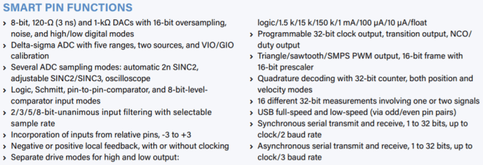
- Smart I/O pins (For more details, refer to the “Smart Pin Functions” textbox.)
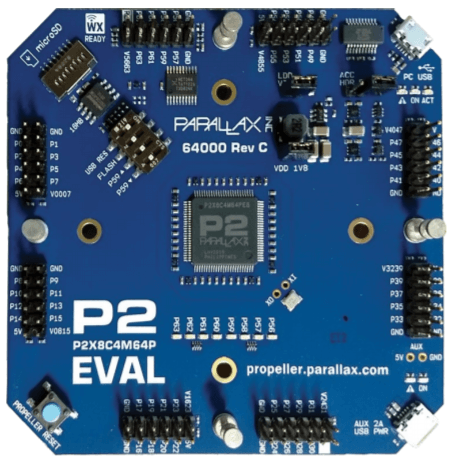
Parallax was kind enough to send us an evaluation kit (Figure 1) with a Revision C engineering sample on it, so that we could have a first look at and start playing. So I will use this article series to give you some insight into the chip, its peripherals, sample code, and more.
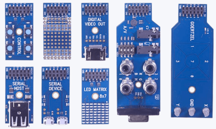
A word of warning: as I write this, the chip is officially not released, so you should expect that we will hit some rough spots when it comes to software that might still be under construction. We were provided with not only the evaluation board, but also a stack of add-ons to test and play with (see Figure 2).
Where have the peripherals gone?
Wondering where the SPI, I2C and UART modules are? Those can be formed by using the smart pins and some code inside the cogs. Even if they are not directly on the feature map, they are available. With this approach we will be able to output an HDMI signal directly to a monitor and display content from a flash chip. But that is planned for the end of this series. As an introduction to the individual peripherals and their special features will be quiet long and boring at the beginning, we are going to introduce them while we move along with the Propeller 2, so introducing them “on-demand.” The next step will be a short look at the development environment and getting our first I/O pin to drive an LED.
Discussion (0 comments)