
Build an Analog ESR Meter With Moving-Coil Meter Precision
on
I was always envious of my friend’s analog ESR meter that allowed him to check and find bad capacitors while they were still in circuit. The particular meter he had is no longer available, which meant doing some research to understand how they worked and to come up with my own version.
First, What Is ESR?
ESR stands for the equivalent series resistance of a capacitor. ESR is frequency-dependent, temperature-dependent, and changes as components age. It’s typically important for ‘wet’ aluminum electrolytic capacitors used in power supplies to have a low ESR.
The typical method used for measuring ESR is to supply the capacitor with a known AC current (Icap) at some frequency where the capacitive reactance of the capacitor is very low so that the ESR dominates. By measuring the resulting AC voltage developed across the capacitor’s terminals (Vcap), the ESR can be determined with Ohm’s law:
ESR = Vcap/Icap
Most of the designs I found worked along the same lines as the block diagram shown in Figure 1. Going from left to right, there is an oscillator that supplies AC voltage to be applied to the capacitor. Next, the AC signal is fed into an impedance converter and detector. The detected signal is then rectified and buffered so that it can drive the meter on the right of the diagram.
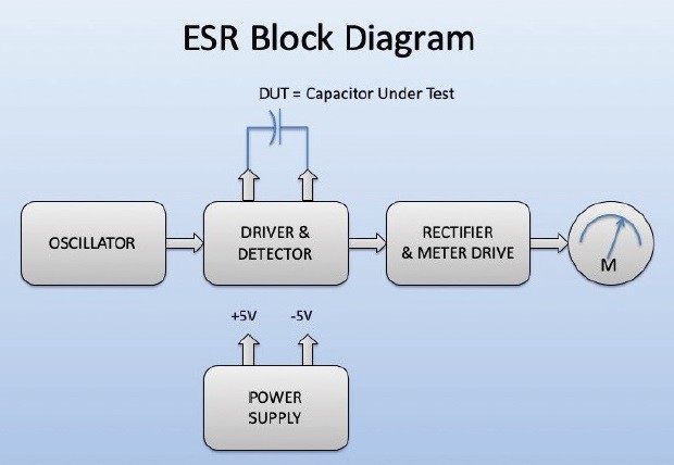
Since the ESR meter is to be battery operated, the power supply circuit supplies split rails for the operational amplifiers that will be used in the ESR meter. The oscillator in most of the examples I looked at operated at 100 kHz to 150 kHz. The driver used to reduce the impedance of the AC signal could be anything from a transistor current boost, transformer, or paralleled logic gates. The detector was usually back-to-back diodes. The detected AC signal is then rectified, amplified and fed into a DC meter.
My Circuit
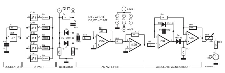
In the circuit I decided to build (Figure 2), I used several design elements from the DIY examples I found on the Internet. For the oscillator and impedance converter, I used a single 74HC14 that provides six inverters with hysteresis. One of the inverters acts as a relaxation oscillator and the remaining five inverters operate as the impedance converter. This part of the circuit came from Lawrence P. Glaister VE7IT. His circuit and article can be found at http://ve7it.cowlug.org/esrmeter.html.
DIY examples found on the Internet.
The detector portion of the ESR meter is the same as the detection circuit in the commercial ESR meter built by Creative Electronics. Sadly, these meters are no longer made.
Diodes D1 and D2 clip the top and bottom of the 100 kHz AC to one silicon junction drop. This allows capacitors to be tested in circuit because any other silicon junctions will not be forward biased by the relatively low AC signal. The low-level AC signal is DC decoupled with C3 and amplified by two operational amplifiers, with a voltage gain of 4.7 for the first amplifier and a gain of 10 for the second. This provides an overall gain of 47 to the input of the absolute value circuit.
The absolute value circuit was taken from the Burr-Brown Application Bulletin “Precision Absolute Value Circuits." The absolute value circuit had plenty of drive for the 100 microamp meter I used.
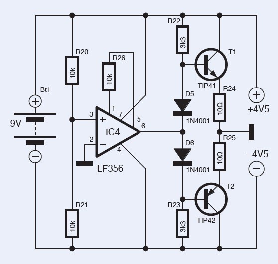
This ESR meter operates of a single 9-volt battery. The plus, minus and ground voltages needed for the operational amplifier are derived using the opamp voltage follower with current boost shown in Figure 3.
Test and Operation
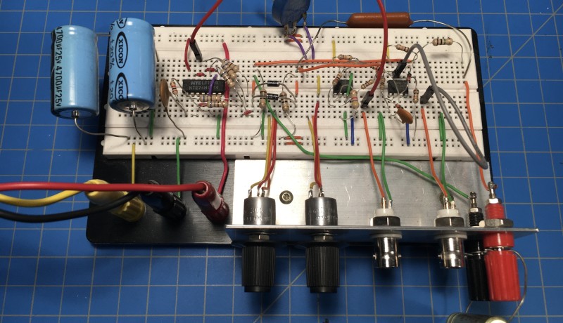
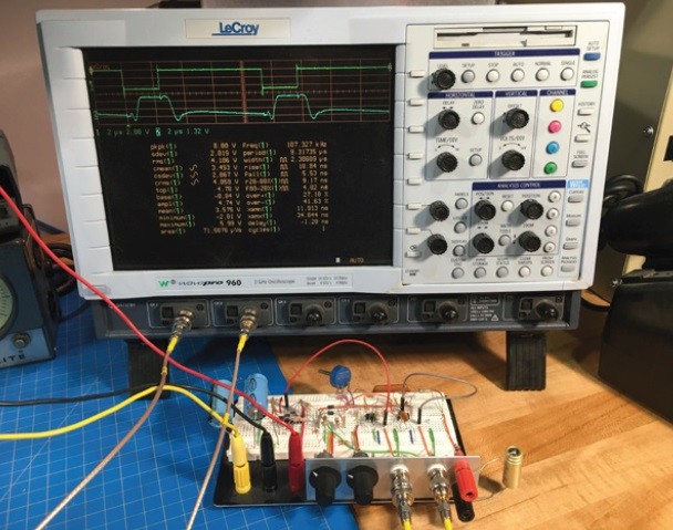
To test out the circuit, I built it up on a conventional bread board. BNC connectors allow for easy monitoring of the various waveforms. Initially for testing I simply looked at the signals with an oscilloscope instead of the 100 µA meter (Figures 4 and 5).
of the ESR meter while testing a 50 μF electrolytic capacitor.
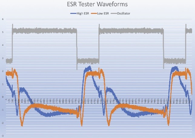
with a high ESR in blue and a capacitor with a low ESR in orange.
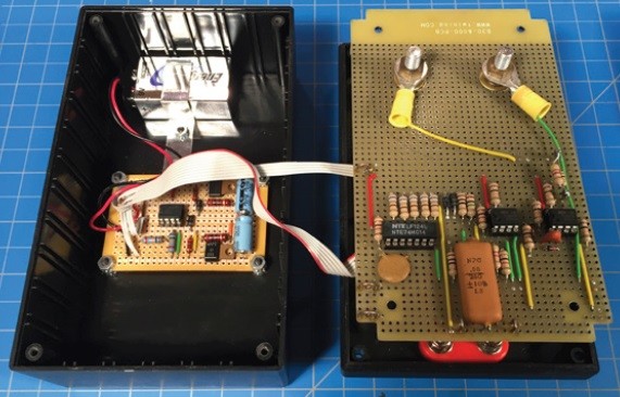
The circuit is wired on two prototyping perfboards (Figure 6). The smaller board on the left is the circuit used to derive the plus, minus and ground references for the op-amps. The larger perfboard is the ESR meter circuit and is held in place by the nuts on the meter.
Even before I was able to package the meter into a case I used it to trouble shoot our air conditioner by locating a bad motor capacitor (Figure 7).
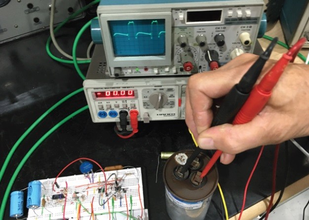
useful when checking the motor capacitor of an air conditioner.
The completed ESR meter is sufficiently portable so that it can be used remotely and away from the work bench. Simple Post-It Note calibration was accomplished with a handful of 2-Ω resistors (Figure 8).
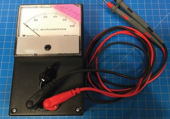
2-Ω resistors and a scrap of paper.
The ESR meter works like an ohm meter. Before measuring a capacitor, the leads are shorted together and the knob is adjusted for a full-scale reading (zero ESR). Rotating the knob fully counter clockwise turns the meter off with a switch.
(210017-01)
Editor's note: The complete article, "Simple Analog ESR Meter With Moving-Coil Meter Precision," appears in the July/August edition of Elektor. Become an Elektor Member today!
Questions or Comments?
Do you have technical questions or comments about this article? Email the author at glydeck@aol.com or contact Elektor at editor@elektor.com.
Discussion (0 comments)