
A Simple DDS Signal Generator: Direct Digital Synthesis in Its Purest Form
on
Want to build a signal generator? Follow these tips about constructing a high-performance direct digital synthesis (DDS) signal generator using an AD9851. The topics of module modification, theory of operation, and software are all covered in this article about constructing a DIY DDS signal generator.
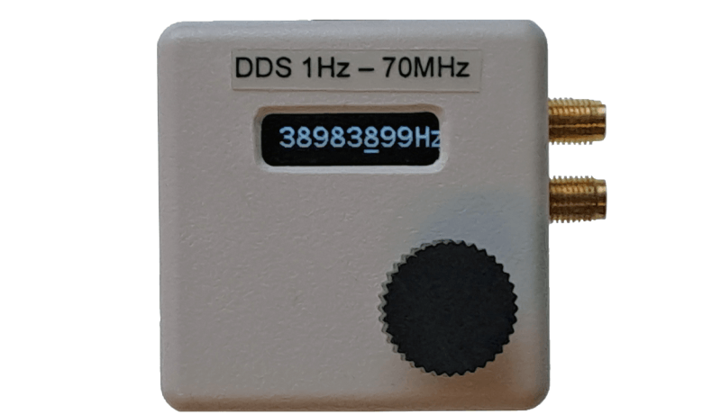
Analog Devices offers a range of integrated circuits containing complete DDS signal generators. These ICs cannot operate by themselves, but need a low-pass filter and a controlling device for initialization and setting of the desired output frequency. At AliExpress, complete modules are offered carrying the AD chip together with the filter and some other components for a very competitive price. In the little signal generator described below, a module with the AD9851 is used. This module can produce a sine wave signal with a frequency of between 1 Hz and 70 MHz. A comparator is present on the chip, which compares the sine wave output signal with an adjustable DC voltage, thus producing a square wave with an adjustable duty cycle. The addition of a small microprocessor, a rotary encoder, and a display makes a complete signal generator.
What’s Under the Hood
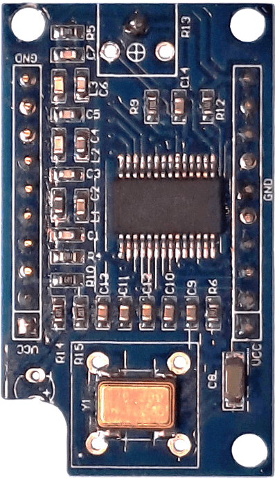
Signal generation is accomplished by direct digital synthesis (DDS). It uses a numerically controlled oscillator (NCO) and a lookup table (LUT) to produce a digital sine wave. The latter is converted into analog form with a digital-to-analog converter (DAC). The AD9851’s datasheet provides more detailed information. Figure 1 shows the module with the AD9851. To make it fit into the selected enclosure, the LED was removed and a corner of the module was cut off. The potentiometer for adjusting the comparator’s DC input voltage was removed as well, as it was not needed: That DC voltage will be generated by a DAC within the microcontroller used to control the module
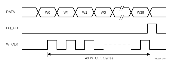
The AD9851 can be controlled in either a parallel or a serial mode. Since the serial mode needs only four connections and the parallel mode more than twice as many, we use the serial mode for initialization and frequency selection. The “serial load” signals, as they are called in the datasheet, are shown in Figure 2. The fourth signal resets the device to initialize it. A microcontroller provides these signals using the built-in SPI peripheral. Since the frequency will be variable, a rotary encoder is used to allow the user to change it. A small display is added to show information on the currently selected frequency. One should be aware of the fact that a DDS signal generator does not produce pure sine wave signals — the output signal contains multiple harmonics of the sampling frequency.
A Look at the Circuit Diagram
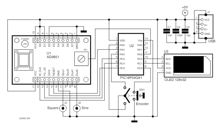
Figure 3 depicts the schematic diagram. Because only a limited number of IOs is required, a Microchip PIC18F04Q41 14-pin microcontroller is used. It controls the DDS module with four outputs, reads the rotary encoder with three inputs, and drives the display via the I2C bus, which needs another two outputs. The DC output voltage is generated on pin 11.
The last pins remaining are 1 and 14 for power supply and 12 and 13 for programming. The PIC18F04Q41 can be programmed with a PICkit 4, PICkit 5, ICD 4, ICD 5, or MPLAB Snap. Earlier versions of these tools are not compatible with this PIC. The processor was programmed before mounting on the PCB. It is possible, however, to program the processor on-board by temporarily soldering wires to the processor pins and then desoldering them after programming. The 5 V supply voltage is provided via a USB connector.
The PIC18F04Q41 belongs to a new series of PICs. In particular, the serial IO modules for SPI and I2C have been improved compared to older devices. This is very useful in this application. The SPI module now has a buffered output register, giving us the opportunity to produce the required forty-bit serial output signal in a single continuous stream. For this serial signal, a clock of 16 MHz is used, so that a change of the generator’s output frequency takes less than 3 µs. Also, the I2C module is easier to set up than with the older type PICs. The current frequency of the generated signal is shown on a small 0.91″ OLED display, which is controlled via an I2C bus with a clock frequency of 400 kHz.
How to Change Settings
Pressing the rotary encoder’s knob moves an underline cursor from left to right, circling back to the left when the far right is reached. Turning the encoder will increase or decrease the number underneath and to the left of the decoder. This provides an easy way to quickly cover the total range from 1 Hz to 70 MHz. Any change of the displayed number will cause an output signal to the DDS module to adjust the output frequency accordingly.
As mentioned, the DC voltage that goes to the input of the comparator on the module is produced by a DAC inside the microcontroller. This voltage can be changed by pressing the encoder’s switch for about two seconds until the display shows a three-digit number. In this situation, the voltage may be adjusted in 256 steps by turning the encoder until the square wave’s duty cycle is as desired. Pressing the knob again for longer than two seconds makes the display return to frequency display. The value of the selected DC voltage is stored in the PIC’s internal EEPROM.
Construction
The circuit uses only a few components. A small printed circuit board was made so that everything could be put into a little enclosure made by Strapubox, with dimensions 50×50×20 mm3. Two SMA connectors serve as outputs. There would not have been sufficient space for BNC connectors. As shown in Figures 4a, 4b and 4c, the encoder’s connector pins have been bent 180˚ so that they can be soldered to the PCB. This must be done carefully, since they break easily.
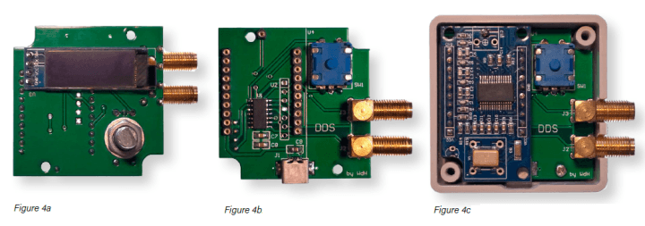
One of the mounting screws used to attach the PCB to the enclosure is covered by the DDS module. Therefore, the latter has been made pluggable. Here, we run into a space problem: The enclosure is only 20 mm high. Using an ultra-low-profile socket connector and accompanying low-profile pins, the height could just be kept within this restriction. The microprocessor is only available in an SMD package. The three capacitors and the USB connector are also SMDs, which made the layout very simple.
Firmware
The firmware has been written in assembler and occupies only 13% of the processor’s program memory. At first, the ports are set up and then two configurable logic cells (CLCs) are set as flip-flops that detect any positive transient caused by turning the rotary encoder. Hereafter, timer2 is configured to provide a 10 ms delay for debouncing the switch, and timer4 to set a delay of about 100 ms. The latter is required after initializing the OLED display. After setting up the DAC that produces the DC voltage for the comparator, the I2C bus module is configured to communicate with the OLED display with a clock frequency of 400 kHz, and finally the SPI module that controls the DDS module. After this, the display, the DDS module, and the interrupts are initialized.
Everything is completely interrupt-driven. The program section consists solely of NOPs. Here, the processor waits for interrupts. The switch’s interrupt service routine moves the cursor to the right. If the switch is pressed longer, the output value of the DAC is shown as described above. If the flip-flop of the second CLC changes state, the second interrupt service routine will run. The CLC’s output status indicates whether the displayed frequency value has to be incremented or decremented. After displaying the new value, the control bytes for the DDS module are calculated and transmitted, and the processor starts waiting for the next interrupt.
Editor's note: The article, "A Simple DDS Signal Generator" (230695-01), appears in Elektor May/June 2024.
Discussion (6 comments)