
Small Circuits Revival - Episode 6
December 5, 2019
on
on

An NE555 Watchdog Timer
From an Idea by Wolfgang Borst (Germany)Virtually every modern microcontroller has a built-in watchdog. It prevents the microcontroller ‘hanging’ which may be the result of a programming error or an unforeseen operating condition, where, for example, the program becomes trapped in an infinite loop and no longer reacts to external or internal input. In principle, this built-in watchdog feature is a timer that needs to be regularly reset by a special command within a certain time interval. If this command is not issued it indicates that the program has gone off-piste, the timer times-out and issues a reset. This will then initiate a system reboot.
So that covers every eventuality?
Well, not necessarily, in very rare cases CMOS circuits - and a microcontroller is just that – can suffer a latch-up condition. In this state nothing works and even a reset cannot bring the microcontroller to its senses. If you want to prevent this rare condition, you will need to rely on an external watchdog mechanism. Those of you familiar with the works of Murphy will know that his First Law states that if anything can go wrong, it will. If you ignore the possibility of latch up, it will come back and bite you… eventually.The circuit
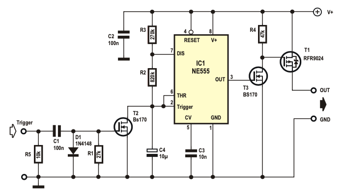
The active component is the good old AMV type NE555. The trigger pulses should discharge C4 before the voltage at pin 6 reaches the threshold (2/3 V +). Otherwise the output pin 3 becomes ‘low’ and T1 shuts off the supply voltage to the microcontroller subsection or the whole device, because T1 can easily handle 1 A without any cooling.
The NE555 is the original bipolar version of the timer which requires a supply of 5 V minimum, the CMOS version of the 555 can operate with a lower supply voltage and is ideal for use with 3.3-V microcontrollers. It also requires less power and can be configured using higher impedance values. In this case make sure the power MOSFET (T1) can be switched with this lower value of gate voltage. If you want to cut down on the number of discrete components in the circuit, try redesigning it using a dual timer IC like the 556.
Read full article
Hide full article
Discussion (2 comments)