
Simulate Circuits Online: Circuit Simulation Made Simple
on
It is often the case that you don't have all the components required to build a circuit that is developing in your mind. Or, perhaps the circuit you wish to develop uses dangerously high voltages and currents. In such cases, it makes sense to use a simulator to test the idea in safety. Simulators are now commonly available, with the Tinkercad Circuits platform covered here accessible in your web browser. As well as simulating circuits, it can also execute Arduino code, as we show here. Circuit simulation made simple!
SPICE (Simulation Program with Integrated Circuit Emphasis) is the best-known software for simulating analogue and digital electrical circuits. Unfortunately, it is not that user-friendly and it requires the circuit diagram to be expressed in its own special format. So it is good news that a graphical interface, Tinkercad Circuits, has been developed that allows you to use it online. There is no need to install any software and you can build your circuit exactly as if it were on a breadboard. It also also offers integration of ATmega (as used in the Arduino Uno) and ATtiny microcontrollers. You can write and execute your programs in C or C++, or simply use the Scratch visual programming language.
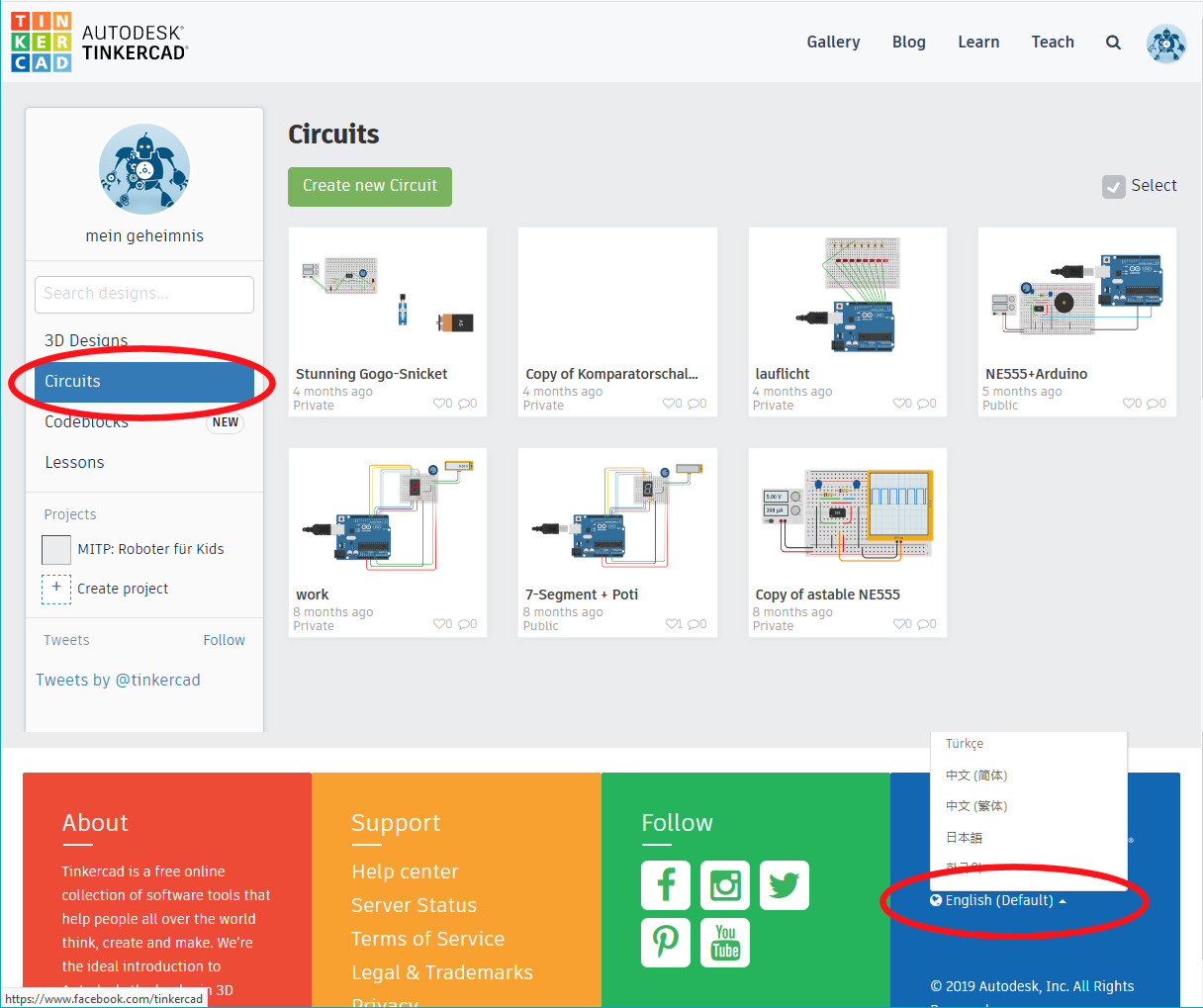
Start by logging in to the website https://www.tinkercad.com. You can either create a new account or use a third party account such as Google. From the dashboard, go to the area called Circuits. At the bottom of the screen you can change the user interface language if you wish. As a new user you will not have any designs visible.
The project created for this article can be found at https://www.tinkercad.com/things/az1gBrXUclZ.
- Click on ‘New circuit’. The breadboard view is similar in many ways to that offered by Fritzing. Therefore, it is a good idea to get to know Fritzing and read our article about that tool it in the previous issue.
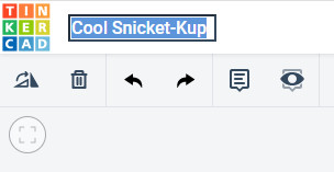
- Your design will be permanently stored in the cloud. At the top of the screen next to the Tinkercad logo you will find that a made-up name has already been assigned to your project. You can click on the text there and change it to something more appropriate.
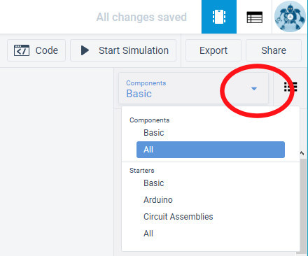
- On the right-hand side you will see a selection of example projects and components. Under Basic in the selection list you can find a number of examples that you can try out. Since we are creating a new project from the beginning choose All under Components.
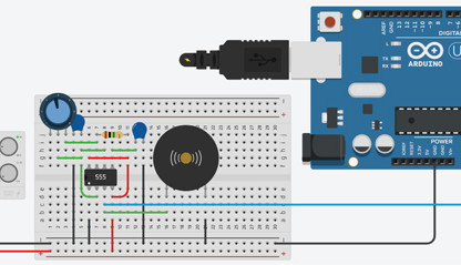
- From the component selection list choose a power source (bench supply), the Arduino Uno R3 and the small breadboard. Click on each symbol in turn and place them in the working area.
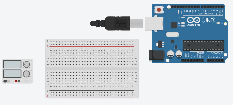
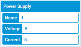
- In many cases it is possible to adjust the parameters of a component such as colour, type or dimensions by clicking on it in the working area. This opens a small dialogue box showing the settings that can be changed. Click on the power supply and set the Voltage to ‘5’. You can also use a decimal point for this value if required.
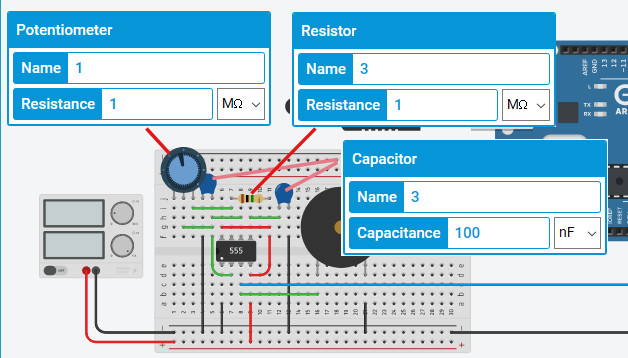
- Place the components and the wiring on the breadboard. In the diagram you will see which values can be changed for each component.
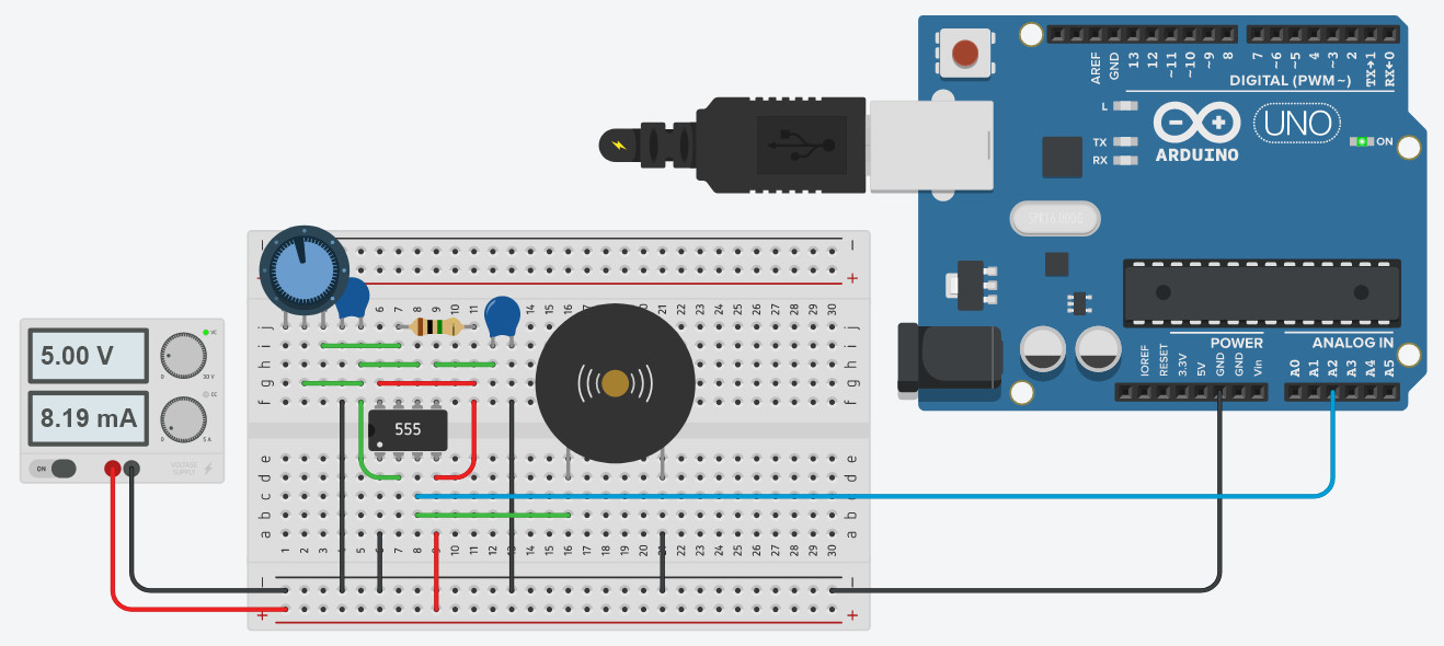
- A common connection to the GND pin on the Arduino is also required (black line running off to the right) as well as the (blue) connection to pin A2.
- When you have finished building the circuit you can test its electrical functions and simulate it. Just click on Start Simulation at the top of the screen. A brief animation will show the USB plug being plugged into the Arduino to show that it is now being provided with power, and the ‘ON’ LED will light. At the moment, however, there is no program for the Arduino to execute. The power supply will also show its output voltage and the instantaneous current being drawn.
- You can click with the mouse on the controls of the power supply and drag them around. The main part of the circuit will withstand up to around 18 V, but not the Arduino connected over the blue wire. In real life you would destroy the microcontroller like this, but in this simulation you cannot do any damage. The piezo sounder will emit a spluttering sound if you have a loudspeaker connected to your PC. You can use the mouse to adjust the blue potentiometer at the top left of the breadboard: as you turn it, the sound will change.
- Click on Stop Simulation and then on Code (next to it on the left) to open a window that will allow you to enter source code. The ‘code view’ will slide in from the right-hand side and, initially, you will be presented with the Scratch editor. At the top you can change to Text (note: a warning will pop up, which you can dismiss).
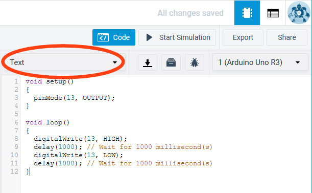
- A small amount of ready-made code will appear in the window. Delete all of this and replace it with the following commands.
const uint8_t iopin = A2;
void setup()
{
pinMode(iopin, INPUT);
Serial.begin(9600);
}
void loop()
{
Serial.println(digitalRead(iopin));
delay(10);
}
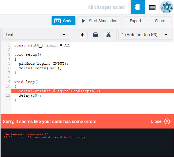
- When you next click on Start Simulation the program code will also be executed. If there are any syntax errors in your program they will be highlighted in the same way as in the Arduino IDE and must, of course, be fixed before continuing.
- In this example the Arduino will behave as a simple oscilloscope, printing out the signal it sees on its input pin. This corresponds to the signal that is driving the piezo sounder. Click on the bottom of the code view window on Serial Monitor and you will be able to see the sequence of ones and zeros. In the far bottom right is a waveform icon. Click here to see a graphical representation of the signal.
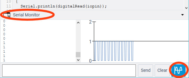
- Turn the potentiometer and, as the sound changes, you will also see the displayed waveform change.
This article about circuit simulation originally appeared in German in a special edition of Elektor offering an introduction to electronics based on the Arduino platform. The English edition is now available: https://www.elektor.com/elektor-special-introduction-to-electronics-with-arduino.
More on Arduino and Circuit Simulation
Want to learn more about topics like Arduino and circuit simulation? Take out an Elektor membership today and never miss an article, project, or tutorial.
Discussion (2 comments)