
Small Audio Mixer: A Versatile Scalable Design
on
Two Versions
The first version of this project was made with Alps RK09 series potentiometers, and consisted of only two PCBs. The first board housed the level and pan pot controls. The second handled the mix and master volume. This former version of the project, with one mic input and two line inputs, was used to monitor my field mixer for a Smartphone DI Box project.
The second version of the audio mixer was implemented using Bourns PTV111 series potentiometers and adapted following the feedback from a Labs reader concerning the negative influence of the pan pot on the level control. By inserting a buffered op amp between these two potentiometers, the problem was solved. So, instead of using a single NE5534 opamp, I added an input preamp stage, switching to the dual, low-noise operational amplifier NE5532 by Texas Instruments.
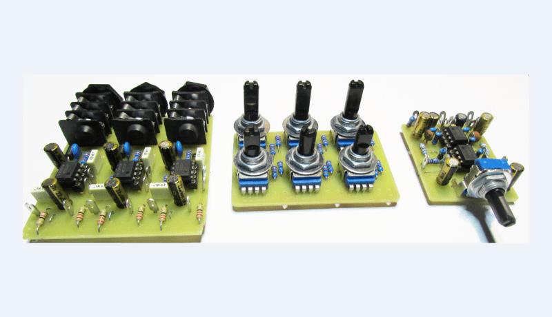
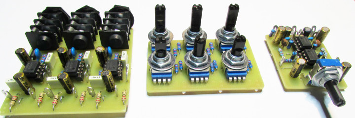
This new version of the Small Audio Mixer consists of three boards, as shown in Figure 1:
- Input
- Level & Pan
- Mix & Master
Circuit Diagram
The circuit diagram is depicted in Figure 2. Although I started the preamp with an NJ5FD-V jack, I quickly switched to the NRJ6HF model due to size, availability, and price. I used the TN pin so that in the absence of a signal, the input is grounded.
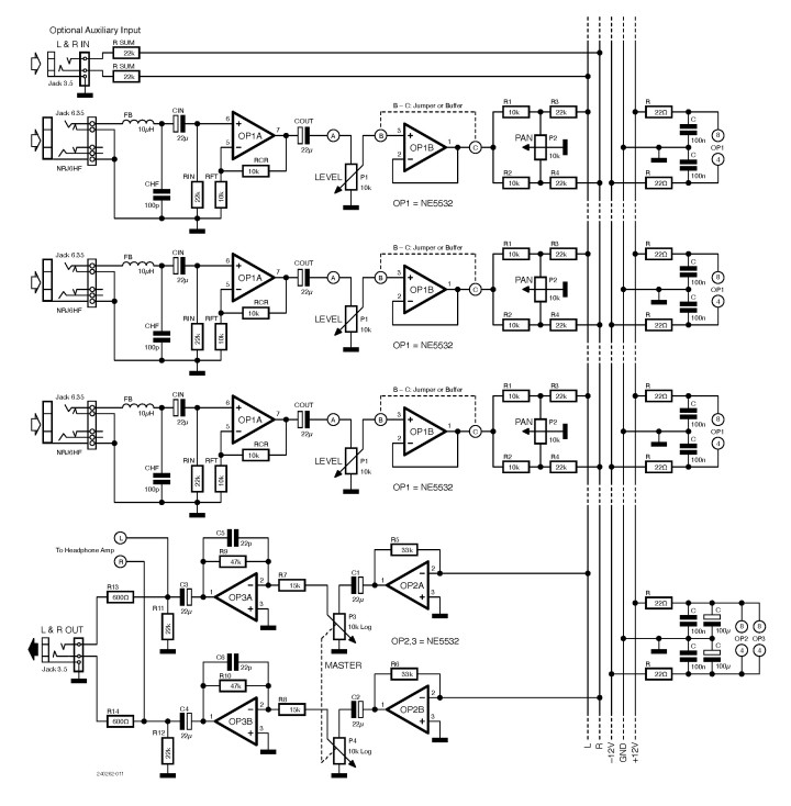
I placed a small LC input filter consisting of a ferrite bead (or VK200) and a 100 pF X7R capacitor. CIN (22 µF) cuts off any DC component. The silkscreen of the Input/Preamp PCB is shown in Figure 3.
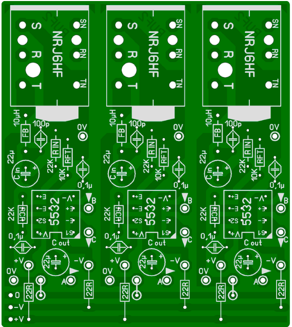
TN pins of NRJ6HF jack connectors.
RIN (22 kΩ) sets the input impedance. You can adapt its value, according to your sources. The gain of OP1A is calculated as 20 log (1 + RCR/RFT) or 10 dB. For example, you can have a gain of 30 dB with RFT = 1 kΩ and RCR = 47 kΩ to build an instrument preamp. In this case, RIN can go up to 100 kΩ or more (see instrument characteristics) and CIN can go down to 1 µF.
The output of the preamplifier OP1A goes to the LEVEL potentiometer P1 (A) located on the Level & Pan board, shown in Figure 4. From the cursor of P1 (B), the signal is fed to OP1B, that works as a unity-gain buffer, to avoid any influence on the level resulting from the adjustment of PAN pot. But this buffer remains an option, which can be replaced by a jumper (B-C) under the potentiometer PCB.
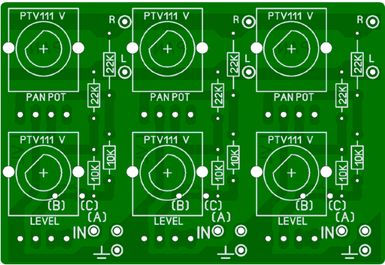
Bourns PTV111 series potentiometers
R1 to R4 and P2 constitute the pan potentiometer’s circuitry. When the cursor is on the right, R1 is grounded, thus putting the left channel at 0 V potential via R3. When the cursor is on the left, R2 is grounded, thus putting the right channel at 0 V potential via R4. In the mid-position, there is a balance of the left and right signals. In this central position of the PAN pot, the signal is attenuated by 10 dB since R1 (10 kΩ) and half of the potentiometer (5 kΩ) constitutes an attenuator whose formula is: 20 log (10 k + 5 k) / 5 k = 20 log 3. The same applies to the calculation with R3. No problem because the preamp provides a gain of 10 dB and the pan pot a loss of 10 dB: we thus connect to the L&R bus at 0 dB.
Each input module is decoupled by 100 nF capacitors. The 22 Ω R resistors can be used as a shunt to measure the current in each branch of the operational amplifier and cut off in the event of a short circuit.
The input module can be reproduced N-times the number of inputs you want. In my case, the spaces are 20.32 mm between channels but also between LEVEL and PAN potentiometers. Strange? No, we’re in inch steps (8 × 2.54 mm). I always make my drilling plan with my PCB software to be perfectly correlated.
Final Stage
Going forward: OP2A and OP2B are mounted in an inverting-summing configuration, whose gain is calculated: 20 log R5/R3, as well as 20 log R6/R4. The signal is then handled by the Mix & Master board (Figure 5) with the stereo MASTER potentiometer followed by the final stage, which provides a gain of 10 dB (20 log R9/R7 and 20 log R10/R8). This allows to have an output level of 0 dB with the Master control at 70% of its travel and to push the output level, if necessary, in case of attenuated input source signals.
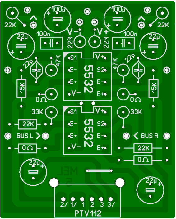
At the output, a headphone amp or other modules can be connected. I also provided a small 3.5-mm jack (L & R OUT) which can be routed to the new generation of a Porta-Recorder. You will notice R13 and R14, two 600 Ω resistors in series with this connector. Their purpose is to avoid overloading the NE5532 in the event of an erroneous connection of a headphone (often 32 Ω or lower, nowadays). These resistors will have little or no effect on the signal of a 10 to 22 kΩ input of a downstream device. RCA cinch connectors can also be considered for this output. R11 and R12 are pull-down output resistors, whose purpose is to avoid any possible voltage build-up at the DC-separating capacitors C3 and C4.
The three terminals A, B, C of the preamp module will be wired with their corresponding terminals on the Level & Pan board. Three boards that can be judiciously placed in a metal housing, preferably. In my case, I’ve used the Hammond 1590DFL (188 × 120 × 56 mm).
Splitting the Preamp, Level & Pan, Mix & Master functions allows me to evolve in my own creations. Increasing the number of inputs is therefore not a problem. I also offer an optional stereo auxiliary input on a 3.5-mm jack. Two summing resistors (22 kΩ) connect the L&R bus. It’s easy to wire directly to this connector. Very practical for adding sources such as a portable radio, PC, tablet, etc. The volume can be adjusted by these devices themselves.
Other Considerations
The phase of the output signal is identical to that of the inputs because in the preamplifier stage we have non-inverting opamps and in the summing, we have two inverting circuits that follow each other. The NE5532 is a must in audio, but there are a host of compatible opamps that could be used for this project. I often test my circuits with TL072s and, if it’s OK, I switch to the NE5532. Using these schematics, you can implement your favorite potentiometers. You can learn more in books like National Semiconductors Audio Handbook or Small Signal Audio Design by Douglas Self.
Let your imagination run wild for your listening pleasure!
Questions About the Small Audio Mixer?
Do you have technical questions or comments about this article or the audio mixer project? Please contact the editorial team of Elektor at editor@elektor.com.
Editor's Note: This article (240262-01) appears in the Elektor Circuit Special 2025.


Discussion (0 comments)