
The New I3C Protocol: A Worthy Successor to I²C or Just More Hot Air?
on
To understand the possibilities and the limitations, you need to remember that the I²C bus has become a completely free technology since the patents held by Philips expired. Although NXP, as the successor to the semiconductor division of Philips, still owns the intellectual property rights to the logo and the name, the technology can now be freely used by everybody.
The discussion about I²C versus TWI has now virtually died out, but there are still interesting comments to be found online with the following tenor: “The concept behind the license fee was to ensure that people who claimed they were making I²C silicon (and selling it as I²C silicon) were supporting the standard and thus helping to grow the standard.”
The results, which are in line with the author’s experience, show that Philips’ aim in collecting the license fee was always to encourage license holders to fully implement the I²C standard. This explicitly included the glitch filter, which in the past was a frequent bone of contention between Philips Semiconductor and third-party manufacturers. This filter (more about this later) may have been one of the reasons why Philips started collecting license fees in the first place. With the expiration of the Philips patents, however, it’s now open season.
Unfortunately, the interoperability of I²C devices in an I3C bus system can only be regarded as either best practice or wishful thinking. Practical tests of such mixed systems are therefore always necessary. First, though, let’s look at who or what is behind the I3C standard.
I3C and the MIPI Alliance
A standardization committee called the MIPI Alliance, which offers a variety of standards for general electronics, is responsible for the I3C standard. The membership fees for this alliance are substantial, as can be seen from the well-hidden list of fees (Figure 1).

To stimulate maximum adoption, the standardization committee offers a completely free basic version of the I3C specification. A list of advanced functions (only available to MIPI Alliance members) can be found at this webpage. On that page you can also see that the abbreviation I3C stands for ‘Improved Inter Integrated Circuits’. In the author’s view, if you use I3C in a commercial circuit, you can only expect to have ‘issues’ with the MIPI Alliance if you implement the interface yourself in one way or another, such as in an FPGA or by bit-banging. If instead you use only purchased components (and do not use the I3C logo or the name in your advertising), you shouldn’t encounter any problems.
Goodbye to Open Drain
Right from the start, the I²C bus has been treating developers to annoyances. Firstly, there is always the question of where the pull-up resistors (needed to charge the bus capacitance) should be placed. Secondly, it is generally not possible to trigger interrupts from a component that does not generate the clock signal. If you want to give a ‘clock sensing’ device the ability to send interrupts, an additional connection is always necessary with I²C. If you have several sensors in the field, this comes at the cost of the GPIO capacity of the clock-emitting component.
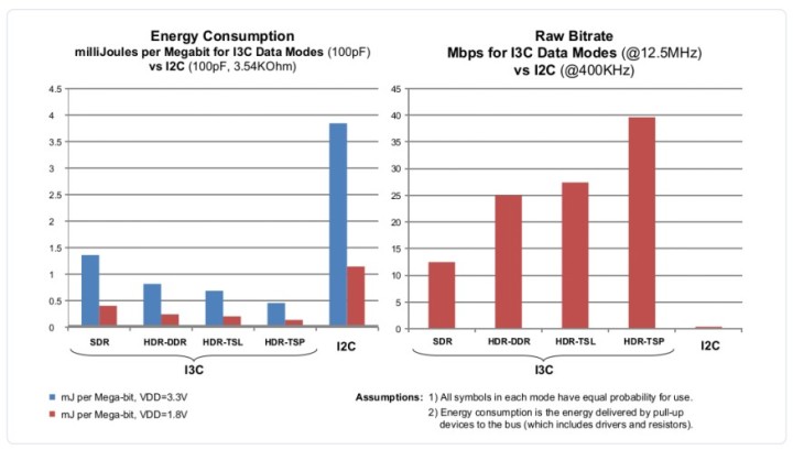
The third annoyance is the relatively low speed: Philips states a data rate of 3 Mbps with an operating frequency of 3.4 MHz. A consequence of this is that the leisurely behaviour of the transceiver leads to high power consumption, since the longer the data exchange between two devices takes, the later they can enter a low-power standby mode. The diagram from MIPI (Figure 2) is, in the author’s opinion, quite plausible.
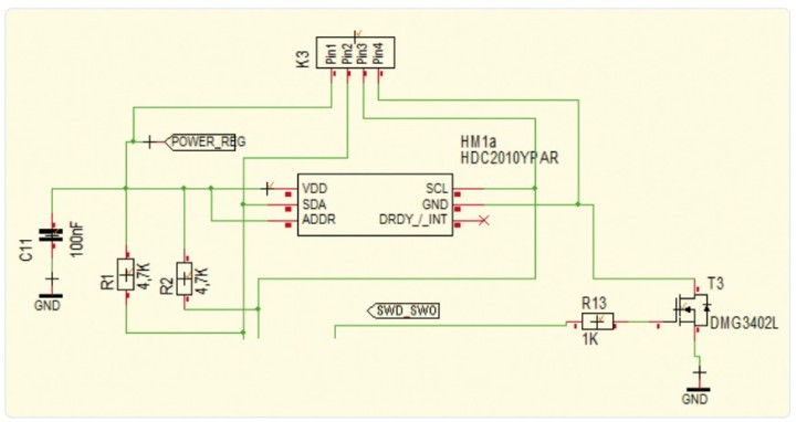
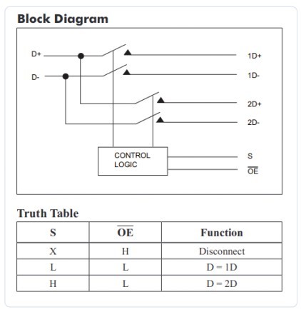
Last but not least, I²C devices have the fatal capability to disable other devices on the bus ‘forever’. A corresponding circuit detail such as that shown in Figure 3 can be found in quite a few I²C systems.
Hello to I3C Improvements
The first change in I3C is that both SCL and SDA work in push-pull mode in most cases. The SCL pin is always push-pull, while the SDA pin also changes to open-drain mode in some conditions. To avoid various problems in the placement of pull-up resistors, the standard specifies that they must always be located in the clock-generating device.
Another important thing (leaving aside special cases) is that SCL is always and exclusively controlled by the clock-generating component. If multiple potential clock generating devices are present on a bus, the clock generating device currently in the active state is responsible for switching the SCL pin.
Clock stretching by the slave device, which is possible on a conventional I²C bus, is not supported by the I3C specification. Operation of such components is therefore not possible on a mixed bus. Then again, the author is aware of only very few use cases where clock stretching occurs in practice.
This simplification is also accompanied by a simplification of the I/O pins on the microcontroller or clock generating device. I²C requires dedicated GPIO pins due to the previously mentioned 50 ns glitch filter, but the MIPI specification only requires normal GPIO pins with the ability to drive 4 mA of current. The specification also explicitly states that glitch filters, which in the case of I²C are often problematic, are not required.
The Rewards of Speed
Now let’s look at the waveforms of I3C. The previously mentioned glitch filter is only significant with I3C if the SCL signal on an I3C bus does not have a duty cycle of 50%, as it usually does with I²C. With I3C the high period is defined as shorter than 45 ns (Figure 4), which logically means that an I²C device implemented according to the standard will not be able to do anything with the SCL waveform.

After receipt of this sort of ‘invisible’ SCL transaction, the clock generating device can also switch its SDA pin or SDA line to push-pull mode and raise the operating frequency to as high as 12.5 MHz. In this sort of full-speed mode, a transmission rate of up to 12.5 Mbps can be achieved according to the MIPI I3C specification.
Higher transmission rates can be achieved with I3C in one of the three High Data Rate (HDR) modes, but these modes can only be used in two special cases. The first special case is a bus system called Pure I3C Bus, consisting exclusively of I3C components, and the second is called Mixed Fast Bus and can also include I²C components – but only if they have a glitch filter implemented according to the specification.
The HDR modes are initiated by a special sequence of SCL pulses while the SDA line is in the idle state. The simplest mode is HDR-DDR (Double Data Rate), which can achieve speeds up to 25 Mbps. This is done by making each edge of the SCL signal a valid trigger for receiving data. HDR-TSP (Ternary Symbol Pure) mode can achieve speeds above 30 Mbps. This mode uses both the SCL and SDA lines in combination for data transmission. HDR-TSL (Ternary Symbol Legacy-inclusive) mode provides yet another special regime that makes TSP more accommodating for mixed buses.
Automatic Address Assignment
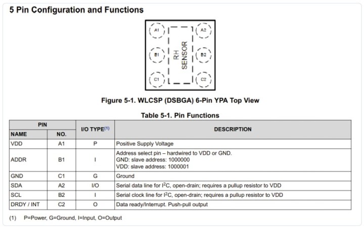
Another annoyance with I²C is that addresses usually have to be assigned physically to individual components. With many components (the HDC2010 shown in Figure 5 is a good example) this means that the address space offered by the standard cannot be fully utilized.
In place of the 10-bit address mode possible with I²C, I3C provides for dynamic self-configuration. In addition, I3C Hot Join capability allows ‘hot plugging’ of I3C devices onto the bus, similar to what is possible with USB.
In the background there is also a procedure called address arbitration that looks after assigning addresses to slave devices. For this purpose each I3C device is allocated three parameters: two eight-bit fields with status information, and a 48-bit unique ID (UID). The specification assumes that each UID (called Provisional ID) is unique on the bus.
When starting up the I3C bus, the clock generating device must enumerate all devices on the bus and assign them dynamic addresses. This is done using a method similar to the arbitration process in I²C: the I3C component with the lowest UID value is first in line for dynamic address assignment. The clock generating device executes multiple assignment cycles until every device on the bus has a temporary ID.
Manufacturer Adoption of the Standard
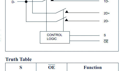
The list of MIPI members is a who’s who in the world of semiconductor manufacturers, from GigaDevice through ST to Solomon Systech. Virtually all relevant companies are on the list. However, if you start looking for practically available components, the pickings are very slim. At Mouser, for example, there are presently only components such as the PI3CSW12 from Dialog. As can be seen from Figure 6, these are generally devices for multiplexing and signal conditioning.
Renesas has, at least for now, also taken a similar approach with devices such as the IMX3102. In addition, the following statement is included in the announcement: “I3C’s 12.5 MHz speeds significantly outpace current and legacy solutions, such as the I²C 1 MHz speed and analog passive quick switches.”
If you’re looking for microcontrollers with I3C support, the list is very short: the i.MX RT685 from NXP is the only option available, and there is an application note (AN12797) that provides example software. NXP also offers a soft core (free in some cases), and there is even a special licence for users who are not MIPI members. If you are prepared to pay for soft core intellectual property (IP), providers such as Silvaco or Arasan Chip Systems offer turnkey I3C VHDL modules.
If you’re looking for displays with I3C support (a use case frequently mentioned in the specification), you won’t find any right now. The only physical hardware presently available consists of some accelerometers (BMI263 from Bosch and LSM6DSO from ST) and the LPS22HH pressure sensor from Bosch.
On the software front, however, things are more encouraging: a relatively detailed description of the interface driver implemented in the Linux kernel is available.
How Long Will It Take? 
The higher data rate and the ability to trigger interrupts without using dedicated GPIO inputs may lead to industry-wide adoption of I3C sooner or later, but the question is how long this process will take. As there are hardly any microcontrollers available now with suitable I3C peripherals, the author’s view is that it could take a while.
Questions or Comments? 
Do you have any questions or comments about this article? Contact the author at tamhan@tamoggemon.com or the editorial team at editor@elektor.com.
210640-01 (planned to be) published in Elektor March/April 2023
Discussion (1 comment)