
Timer for Headphone Amplifier
on
The circuit (Figure 1) is built around a 4093 quad NAND IC with Schmitt trigger (IC1). This device can withstand supply voltages of up to 15 V, more than enough for my purposes. A pair of the gates (IC1a/b) is used to drive the gate of an IRL1404 power MOSFET (Q1) to which the headphone amplifier is connected in the high side as the load (CN2). On the input side of the NAND gates are a capacitor (C1) and a resistor (R3) whose values allowed my amplifier to remain on for about 100 minutes using a 12 V battery. The switch is a sprung momentary ON-OFF-ON SPDT type (SW1). This was used in preference to two momentary push switches that could short the battery should they be pressed simultaneously.

Momentarily pressing the switch in the ‘on’ direction (towards R2) charges C1 via R2 and turns the amplifier on. C1 eventually discharges via R3 at which point Q1 and the amplifier are switched off. Briefly pressing SW1 in the opposite direction (towards R1) quickly discharges C1 via R1 providing a manual method to switch the amplifier off.
Not wanting to waste the remaining NAND gates (IC1c/d) I decided to add a voltmeter that displays the battery status for 2 to 3 seconds when the amplifier is switched on. C2 and R4 provide the timing for this feature while another IRL1404 MOSFET (Q2) is used to power the voltmeter. As Q1 is turned on, C2 charges through R4, enabling the voltmeter via Q2. As soon as C2 is fully charged, the voltmeter turns off again. C2 discharges through the load (my amplifier) and R4 when the load is powered off.
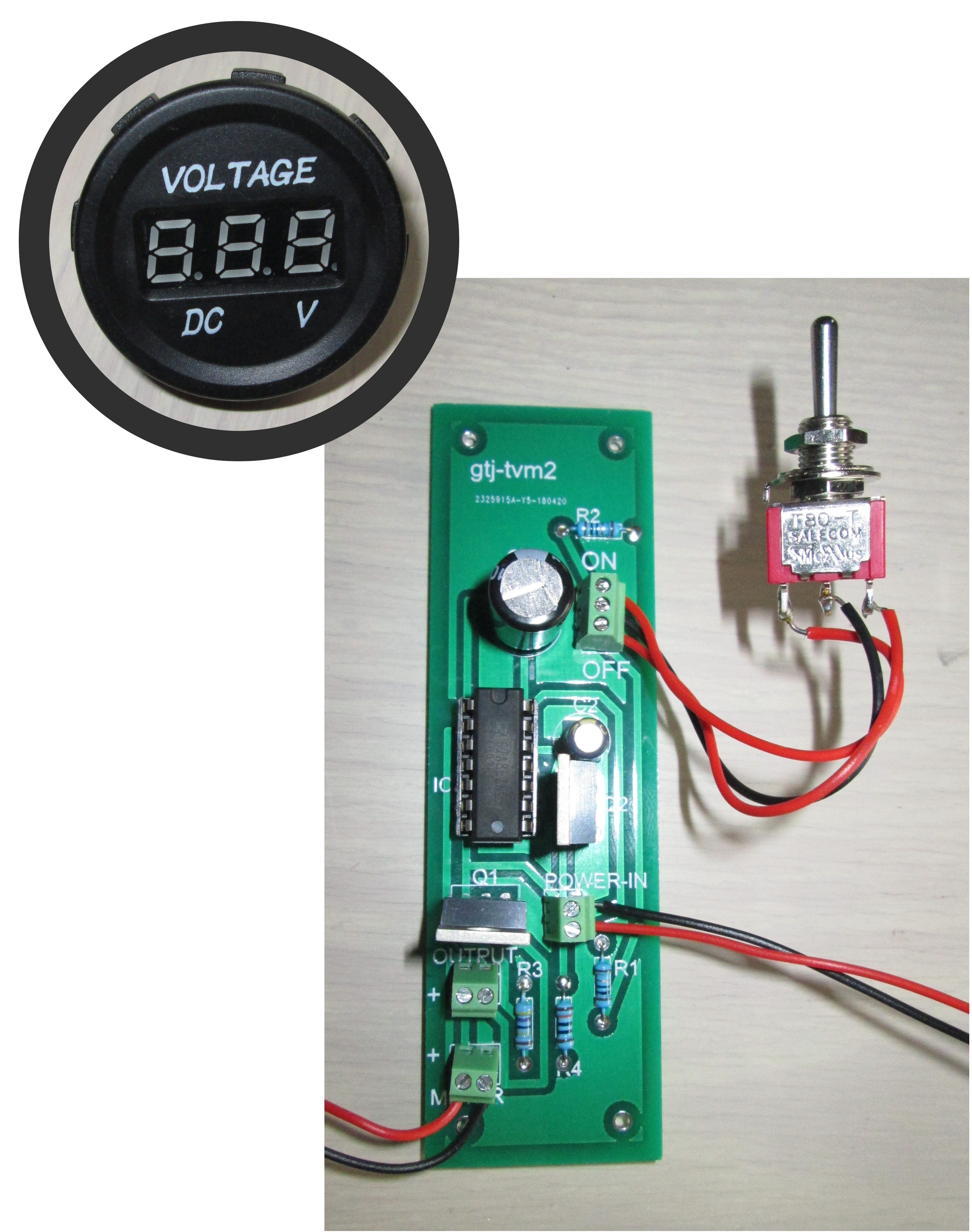
The voltmeter (Figure 2) is a miniature seven-segment LED type that is commonly available at low cost from many online shops. Various types were tested and found to have a current draw of only 6 to 16 mA, so the brief display of the voltage has minimal impact on battery life. The meter chosen featured a circular black plastic bezel that made it easy to mount in a panel.
The MOSFET selected can easily handle any likely current requirements of battery circuits as, according to the datasheet, it can handle currents of up to 100 A. They also handle gate-to-source voltages of up to 20 V, with the gate threshold voltage (VGS(th)) lying between 1.0 and 3.0 V. The Schmitt trigger in the NAND gates ensure that both MOSFETs are either fully switched-on or -off, guaranteeing minimal current consumption. My multimeter can measure currents down to 100 nA, but testing indicated that the current draw when off was below this level.
The drain-to-source on-resistance of the MOSFETs is less than 6 mΩ, meaning the circuit has little impact on the amplifier and that the voltmeter measurement reflects the true battery voltage. Tests with the MOSFETs showed no warming at currents of up to 800 mA, so no heatsink was deemed necessary. Should larger loads be connected to the circuit, the need for a heatsink should be reviewed. I didn’t see any need for a flyback diode for my application but, if you are powering an inductive load, a 1N4007 could be reversely fitted to protect against back-EMF between the drain and source of Q1.
(190030-01)
Want more great Elektor content like this?
Then take out an Elektor Membership today and never miss an article, project, or tutorial
Discussion (1 comment)