
Versatile Servo Tester
on
The general definition of servomechanism, or servo, describes a device used to provide control of a desired operation using feedback. In electronics, and particularly when considering electromechanical actuators, a servo is a device that generates a mechanical motion controlled by an electrical pulse.
Examples of such servos can be found in various fields; for the purpose of this description, I will focus the attention on those used in radio‐controlled models, since they are extremely popular and widely used, not just for models but for hobbies in general. There are several types of servos, analog and digital, with plastic or metal gears, with or without ball bearings, etc. However, all share one thing in common: they can be controlled by the same electrical signal, for all practical purposes.
This signal consists of pulses, of variable width, spaced by a fixed period of time (Figure 1). The fixed period is usually 20 milliseconds (ms), and the pulse width is what effectively controls the servo rotation. The center position is set at 1500 microseconds (µs) for most servos, while the extreme positions could reach up to 500 µs on the lower end and 2500 µs on the upper end. Usually these extremes correspond with the ‐90 and +90 degrees rotation from the center point at 0. Regarding the direction, it could follow the pulse clockwise or counterclockwise, depending on the manufacturer.
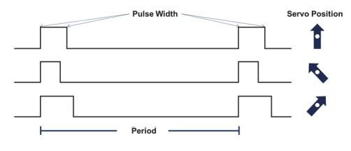
The pulse amplitude, in volts, is usually the same as the servo power supply; the most common supplies are 4.8 V and 6.0 V, although nowadays other amplitudes are possible, from 3.7 V up to 14 V and over.
Why a Servo Tester?
While the manufacturer’s datasheet gives all the specifications of the servo in terms of maximum displacement, speed, dead band, etc., the datasheet is not always available. And this is particularly true for the wide range of low-cost servos currently available on the market. In many cases, although some data may be available, testing the actual performance may give quite different results. At the end of the day, what matters is the actual performance of the servo you will use, not its theoretical behavior.
Designing a Servo Tester
A simple servo tester is something very easy to build, and there are plenty of examples on the web. Suffice to say that with a 555 (very popular integrated circuit) and a few other components, you can create an analog servo tester. However, if you want to measure the servo behavior in a precise way, and with visual indication of the pulse being sent to control it, a slightly more complex approach is required. One step above the simple 555 tester would be one with precise control of the pulse width, including a display showing this value. Cheap versions can be found on the web, but they have one disadvantage: most parameters are already programmed and cannot be changed by the user. Wouldn’t it be great to have a fully customizable servo tester, in which the user has full control of all the parameters to create the desired signal, including manual and automatic testing features?
This is exactly that: a fully programmable unit that allows the user to control all signal parameters, featuring manual and automatic modes, with a clear and intuitive user interface.
Hardware
The full circuit schematic is shown in Figure 2. The external connections are shown in the lower part; to the left is the power input (J5 – DC IN), which can be connected to the ESC of the RC model, or to any power supply capable delivering the required current for the servo under test. The unit uses less than 15 mA, so it will not impose a considerable load to the supply. The voltage can be anything from 4.5 to 6.0 V, depending on the servo requirements.
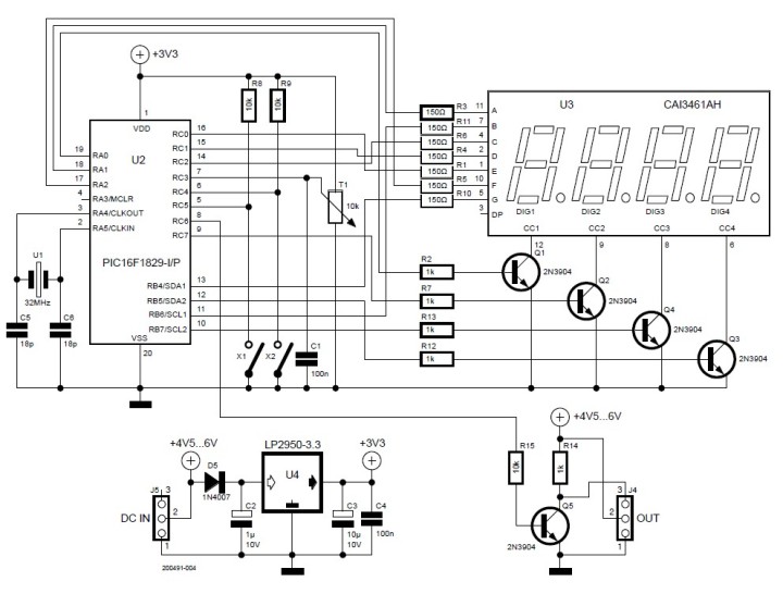
Please note: The servo will receive the full voltage supplied by the power source. Be careful not to exceed the servo maximum ratings! To comply with most manufacturers specifications, the center connector is always the +V terminal, while the extremes are GND and SIGNAL.
The power input only requires two lines, +V and GND, but a 3-terminal connector has been mounted to receive any standard ESC connector. On the right side of the schematic is the servo output (J4 – OUT), with the three lines connected (+V, GND and SIGNAL). This will be connected to the servo under test.
The top‐mid left shows the microcontroller (U2) and the user interface, a single potentiometer (T1) and two SPST switches (X1 and X2). The rotation of the potentiometer will change the pulse duration, while the switches will select the four operation modes, as shown in this chart (the various modes will be explained in the software section):

Finally, the top right is U3: the 4‐digit 7‐segment display, with its required components.
Board Layout
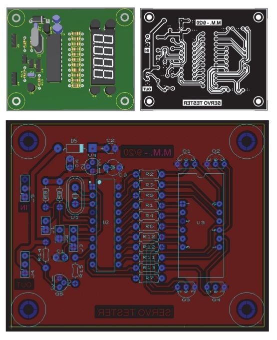
While this hardware can work mounted on a breadboard, a proper PCB design will make it more durable and reliable. A possible PCB layout is presented in Figure 3. The design (NI Multisim) and Gerber files to order the PCB at your preferred supplier are available for download. Please note that the capacitors of the microcontroller’s oscillator circuit are missing in this PCB design; apparently the author’s servo tester also works like a charm without C5 and C6. The capacitors can easily be added on the copper (bottom) side of the board, you may need to scratch the soldermask off the GND-plane. But of course, you can also download the design files and add the two capacitors to the PCB.
- Modes: manual (low and high resolution) and automatic (low and high speed).
- Minimum pulse width: adjustable by software.
- Maximum pulse width: adjustable by software.
- Center position: can be adjusted manually.
- Minimum step/pulse resolution: 1 µs.
- Maximum step: adjustable by software.
- Signal period: fixed at 20 ms.
- Pulse stability/accuracy: crystal controlled.
- Power supply: 4.5 to 6.0 V.
Software
Probably the most important part of this design is the software; here is where the precision and the versatility lie. The program runs in a PIC16F1829, using a 32 MHz crystal as the main oscillator; it is written in C, using the CCS C Compiler. The source code and the HEX-file for programming the microcontroller are available for download.
The program starts with the definitions of hardware and connections, as well as key reference values: The letters a to g represent the 7 segments of the numerical display, while d1 to d4 correspond to the four digits. PWM is the output signal to control the servo and SW1 / SW2 are the switches. The potentiometer is connected to the analog input AN7 (PIN_C3) and it is set in the main function.
At the bottom, there are four very important definitions:
- BRI: brightness of the LED display. This number controls the persistence of each digit (in µs), thus its apparent brightness. It is set at 50 but can be changed from 1 to 200.
- SPD: speed of the servo movement in the auto mode. This number represents the step size (in µs) when incrementing/decrementing the pulse width; the higher the number, the faster the servo moves. Any number from 1 to 100 will work.
- MIN: minimum pulse width (in µs). This will be the shortest value of the pulse both in manual and auto mode. While any number may work, it is recommended not to go lower than 500, since the servo might not be able to reach such extreme.
- MAX: maximum pulse width (in µs). This will be the longest value of the pulse both in manual and auto mode. While any number may work, it is recommended not to go higher than 2500, since the servo might not be able to reach such extreme.
These four parameters add huge versatility to the tester, which cannot be found in any cheap commercial unit. If you mount the microcontroller in a socket, you can easily remove, reprogram, and have a new tester whenever you need it; or, if you are satisfied with one set of parameters, just keep the same program forever.
Each digit is fully defined within a function (num) and can be selected using a switch statement; each time this function is called with a number stored in n, the number will be shown in the display. To select which of the four digits is active at a given time (since the display is scanned sequentially) the function digit includes the selection, also within a switch statement. Whenever it is called, the digit stored in z will be illuminated. If z contains “5”, then all digits will be off; this is used to have a clean transition from one digit to the next, with no “ghosts” in the display.
The function that brings all together (digit selection and number output) is display; this function takes a 4‐digit number, breaks it into the individual numbers and shows them in sequence in the display, from right to left (units first), by calling the two previous functions. Here is where the display brightness is controlled, by adjusting the delay before clearing a digit.
The precise timing of the period and pulse duration is achieved by using TIMER1 interruption. Being a 16‐bit counter, it will overflow at 65536, triggering the interrupt; by preloading TIMER1 with an offset value, a precise time can be measured by detecting this interruption. In sequence, the first time this INT is called we load TIMER1 with the value required for the pulse duration; next time, it will be the remaining of the total period. This process is repeated continuously (controlled by the variable pulse), so a precise pulse width is achieved, while keeping a constant 20 ms period.
Here we also check the status of the switches to decide if we are in auto mode (SW1 = 0). If so, SW2 will determine the speed of the automatic sweep (from MIN to MAX and back to MIN continuously): SW2 = 1 means normal speed (the pulse varies 1 µs at a time) and SW2 = 0 means high speed (the pulse varies SPD µs at a time). You may recall that SPD can be any number from 1 to 100; if set to 1, then normal and high speed will be the same (not very useful indeed).
Finally, main brings all together; besides the initialization of the Analog to Digital Converter (ADC), TIMER1 and interrupts, the main program loop resides here. This loop will read the ADC (thus the value of the potentiometer) and set the pulse duration accordingly.
If we are in manual mode (SW1 = 1), then SW2 is evaluated; if “1”, the low resolution mode is active, and the potentiometer will be able to sweep the full range of the pulse width (MIN – MAX). This mode is called “low resolution” for a simple reason: the ADC can only acquire 1024 different levels, but the pulse width range may be 1400 or more µs, so it is not possible to achieve a 1 µs resolution within the full range. If SW2 = 0, then the high resolution mode is enabled. Here the full pulse width range is limited from 1469 to 1531 µs. The potentiometer can easily be moved to change 1 µs at a time, which is extremely useful to:
- Put a servo in the center point (1500 µs).
- Measure the dead band, how many µs the pulse needs to change to move the servo.
Making It Look Professional
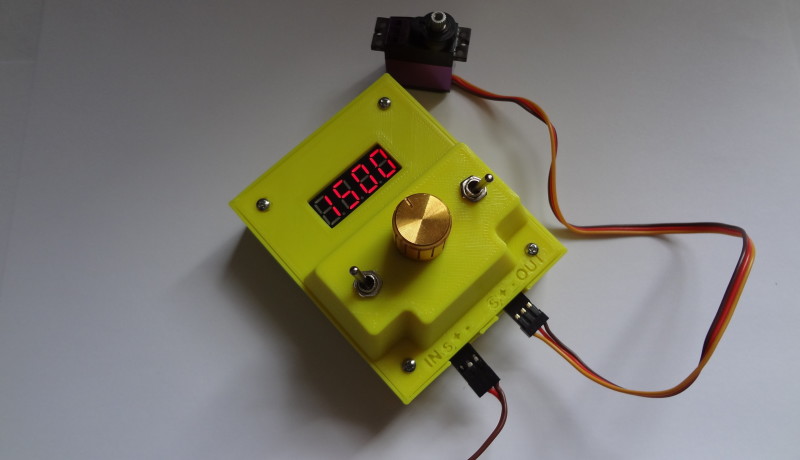
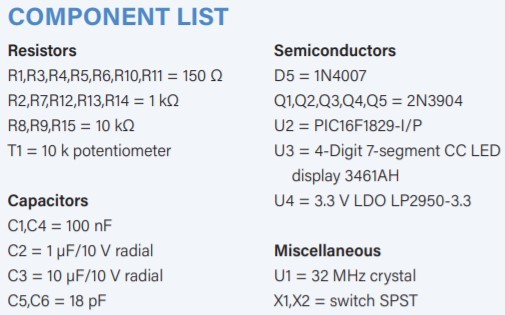
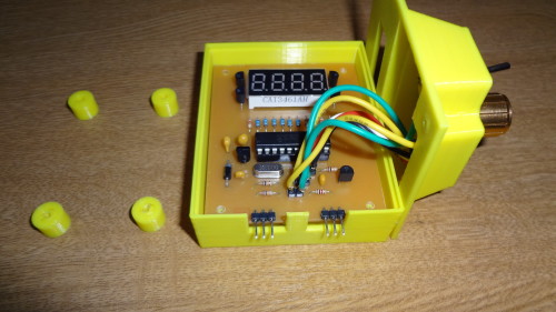
With the proper case, this unit will look quite professional, and it will also protect the hardware. A simple 3D-printed enclosure (Figure 4) will do the job and also this design file is available for download.
The PCB will be ”sandwiched” between four spacers (cylinders) and the bottom case; the top case will be secured with four M2.5 x 20 mm (#2‐56 x ¾) Phillips Pan Head screws. The assembly of the final unit is shown in Figure 5.
Questions About the Servo Tester?
Do you have technical questions the servo tester or comments about this article? Email the editor at luc.lemmens@elektor.com or contact Elektor at editor@elektor.com.
Discussion (0 comments)