
Yes We CAN with PiCAN 3: A CAN Bus HAT for the Raspberry Pi 4
on
A lot of data has flowed under the bridge since Bosch registered the controller area network (CAN) bus specification in 1986 and Mercedes-Benz first used it in its S-Class model in 1991. In the meantime, CAN has become an integral part of automotive development and design. The CAN bus is robust, making it useful for many other fields of application. A mobile CAN bus unit is useful to analyze communications, diagnose problems and control. The PiCAN HAT reviewed here will do the job, and it plugs into the latest version of the Raspberry Pi. Let’s take a closer look.
Vehicle electrical systems are hostile environments for delicate electronic devices. I remember many of my fault-finding efforts, laying 40 m long cables to power oscilloscopes and test equipment running in a car. If you are interested in purely evaluating CAN bus data, the PiCAN 3 now offers an attractive and portable diagnostic alternative.
Why Use a Raspberry Pi?
When you are experimenting with any bussed communication system such as I2C, SPI, etc., problems will occur, not as a result of poor signal quality at the physical layer but in organising and sequencing the transmitted data itself. If you send incorrectly formed packets or get confused how the bytes should be sequenced, for example, you shouldn’t be surprised when the motor or other device you were hoping to control refuses to cooperate.
Tools such as PiCAN 3 in conjunction with a Raspberry Pi allow mobile measurement. Ideally, a Raspberry Pi 4 with a small display monitor is all you need to build a portable test rig. If you integrate the development environment of the CAN system into the ARMbian distribution of the system, then you will be ready to go.
The Hardware Features
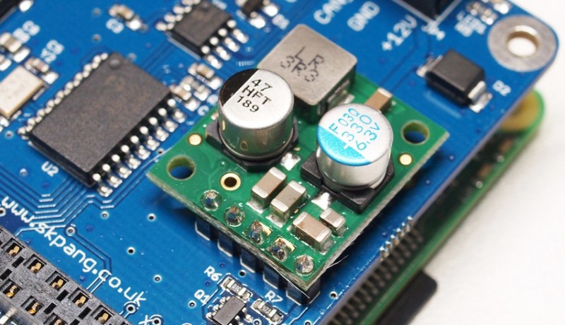
The electrical environment in a car can be quite hostile for electronic circuits The manufacturer SK Pang has taken this into account in the board’s design by incorporating a switched-mode power supply (Figure 1) with a wide input voltage range from 6 VDC to 20 VDC which connects to the board via a five-pin header. The PiCAN HAT should be available without the switching power supply — but currently, this is not the case and the fitted SMPS is standard.
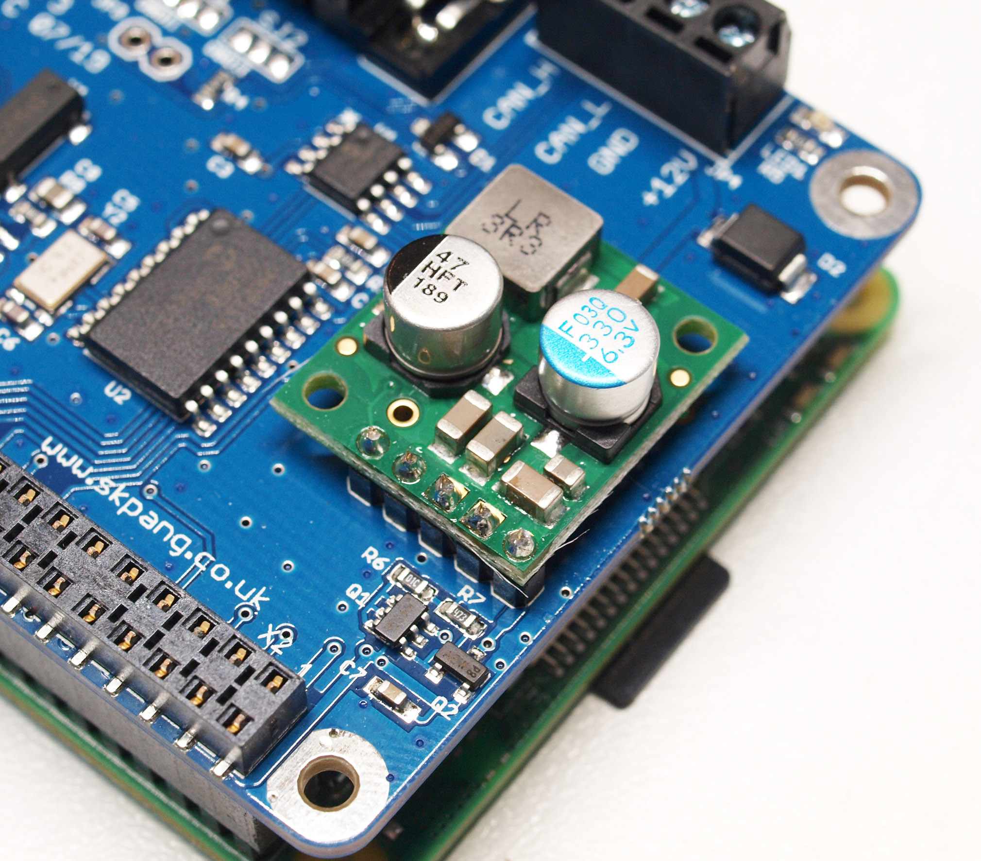
This latest CAN shield is described as the “PiCAN 3 — CAN-Bus Board for Raspberry Pi 4 with 3 A SMPS & RTC” to differentiate it from its predecessors. This latest version includes a 3-A switched-mode power supply to run the power-hungry Raspberry Pi 4. The shield can also be run directly from the Raspberry Pi when it is powered via its USBC port. The board schematic can be viewed at [1] and shows that standard ICs are used throughout the design. The user manual is available at [2].
The CAN signal bus interface is achieved with the MCP2515, which communicates with the Raspberry Pi via SPI and a GPIO interrupt pin. The physical interface with the bus is provided via the MCP2562 IC CAN bus transceiver. The PiCAN3 circuit diagram shows that the 3.3 V power supply used by some components on the board is taken from the Raspberry Pi regulator, thereby saving an additional regulator.
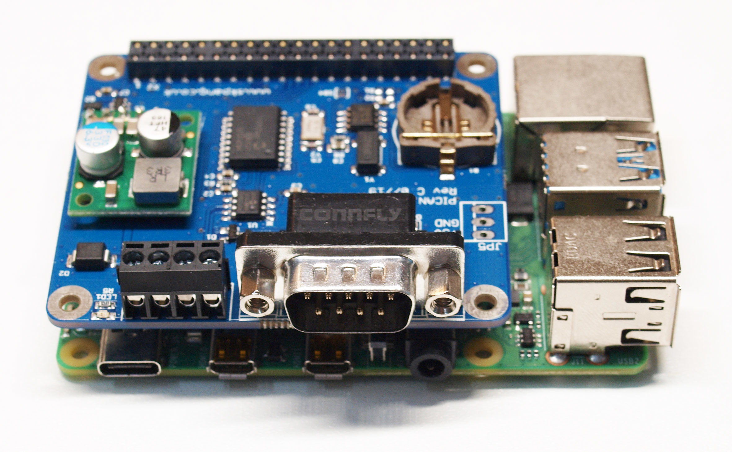
The board provides two connectors (Figure 2) for hooking up the PiCAN 3 with an external CAN bus. Firstly, there is a four-way terminal block with signal identification printed on the board. The second method uses a 9-pin D-sub plug, which many readers over a certain age will recognise as the connector used for standard RS232 communications.
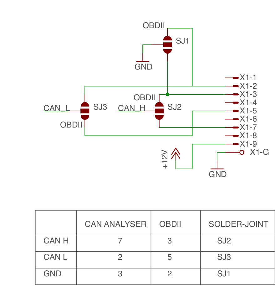
The 9-pin sub-D connector accepts a standard OBD-II to DB9 cable to connect with an OBD system. Unfortunately, there is no standard assignment of the connector pins and CAN signals. To take care of all wiring eventualities, pads on the board (Figure 3) will need to be bridged with solder.
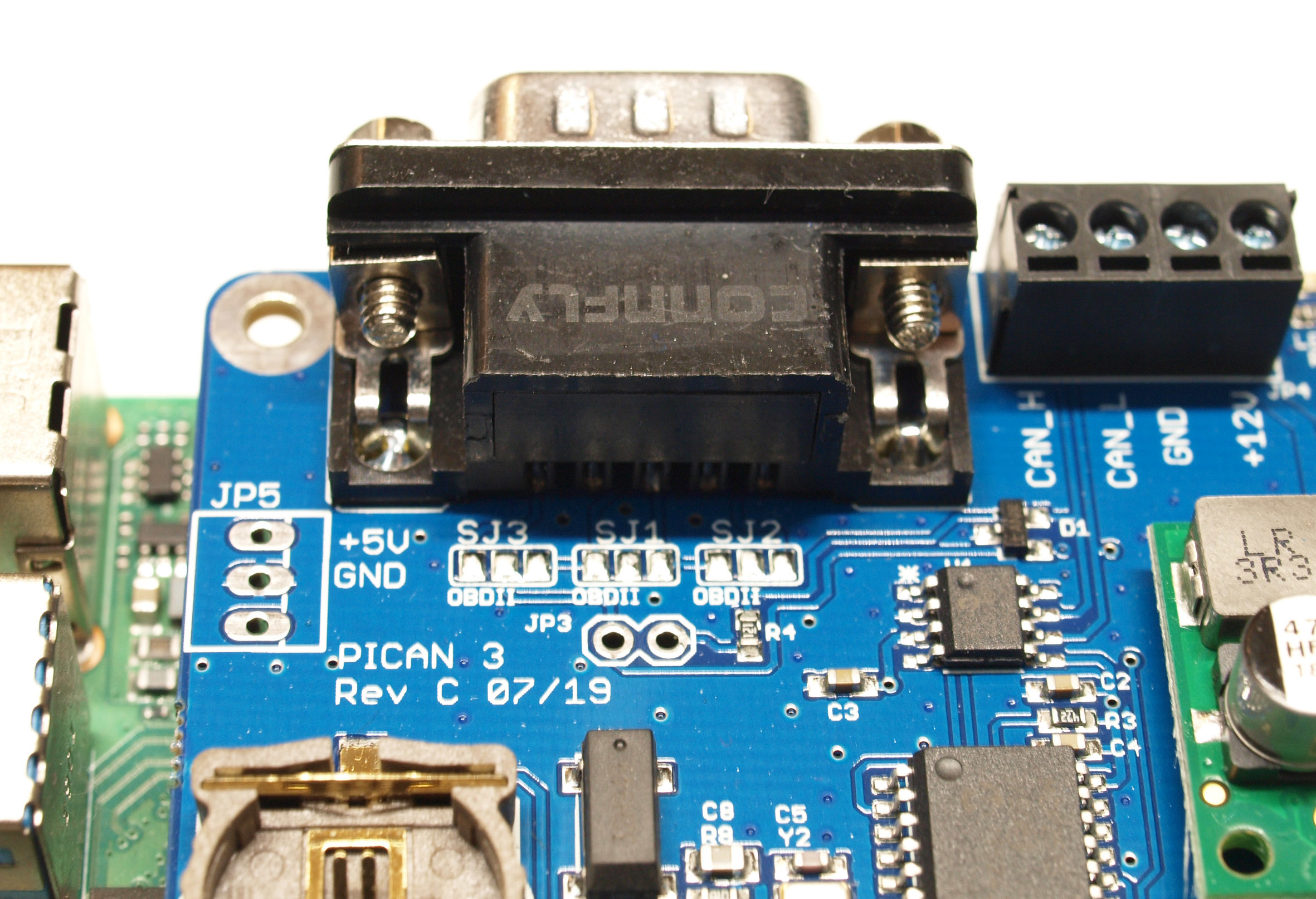
An allocation plan (Figure 4) helps you to decide which pads to link so that the connector is compatible with the system you are connecting to. These pads are completely open on delivery so without the solder bridges the signals will not be routed to the correct pins.
Vehicular applications often require precise time-of-day information. For this a PCF8523 real-time clock chip is used in the PiCAN 3, it talks to the Raspberry Pi via an I2C interface. A coin-cell battery holder is provided on board which accepts a CR1220-type coin cell to power the real-time clock.
The CAN Ecosystem
The Linux operating system has certain relevance in the automotive sector, in fact there is a whole ecosystem in the Linux world to support CAN bus applications. The utilities available range from kernel drivers to command line utilities along with many other useful tools.
To begin communicating with the PiCAN 3, we need to make some adjustments to the /boot/config.txt file of a fresh Raspbian installation. The SPI bus must first be enabled by the following block (note the additional Overlay-call):
dtparam=spi=on
dtoverlay=mcp2515-can0,oscillator=16000000,interrupt=25
dtoverlay=spi-bcm2835-overlay
The following statements are required to use the real-time clock:
dtparam=i2c_arm=on
dtoverlay=i2c-rtc,pcf8523
The next step is to download kernel modules and some other utilities. Fortunately, there is a ready-made package available in the repositories:
sudo apt-get install can-utils
After the deployment of the CAN utilities, the interface must be registered with the operating system. For this it is sufficient to generate a new interface according to the following scheme. The value 500,000 here indicates the maximum data bitrate supported by the hardware:
sudo /sbin/ip link set can0 up type can bitrate 500000
Once the interface is ready, you can use it in the same way as similar products from alternative manufacturers can be used to communicate using the CAN bus. A classic application would be the use of candump.This tool can be activated in the command line by entering the following command:
candump
Once running, it automatically and continuously displays all CAN messages visible to the shield. This is particularly useful for example to reverse-engineer unknown motor control strategies in existing systems.
There is also a Python CAN API that can be installed:
git clone https://github.com/hardbyte/python-can
cd python-can
sudo python3 setup.py install
Adding the Real-Time Clock
The Linux OS has implemented real-time clocks on laptops and PCs for ages. Systems not fitted with a hardware RTC (on the grounds of cost) make use of the fake-hwclock emulator module in the OS to provide time of day information; this is also the case with the Raspberry Pi.
In order to be able to use the hardware real-time clock on the CAN board, we first need to disable “fake” hwclock to stop it interfering with the time provided by the “real” hwclock:
sudo apt-get -y remove fake-hwclock
sudo update-rc.d -f fake-hwclock remove
sudo systemctl disable fake-hwclock
Next we need to open the /lib/udev/hwclock-set file (you normally require Superuser authority to do this) and comment-out the lines of code in these two blocks:
#if [ -e /run/systemd/system ] ; then
# exit 0
#fi
#/sbin/hwclock --rtc=$dev --systz --badyear
#/sbin/hwclock --rtc=$dev --systz
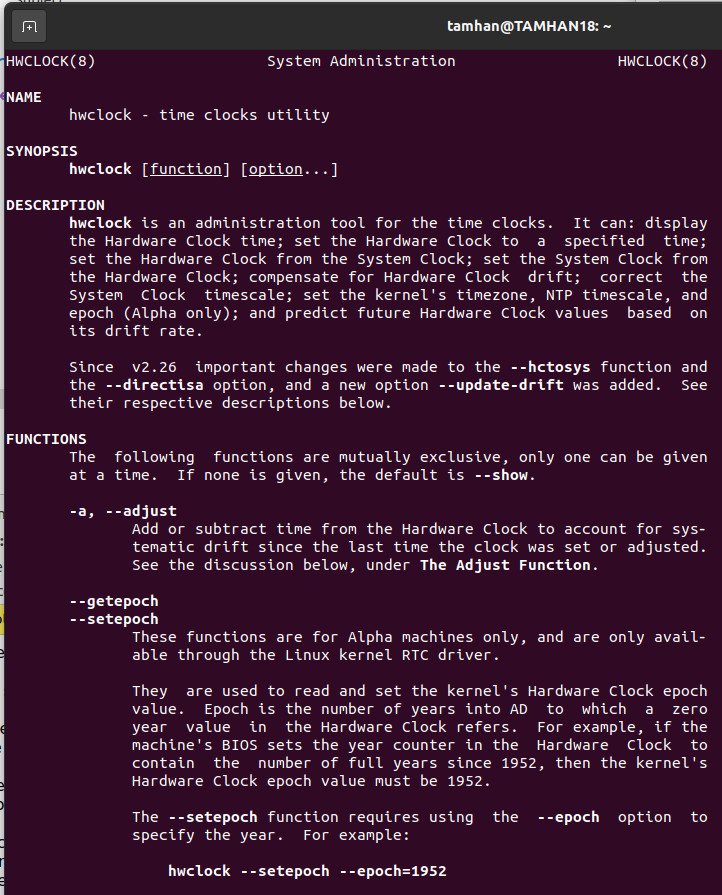
Time information from the hardware clock can now be read using hwclock. The features of this administration tool for the hardware clock is shown in Figure 5.
CAN Bus Communication and Control
The PiCAN 3 HAT from SK Pang with its on-board 3 A SMPS is now suitable for use with a Raspberry Pi 4 to offer CAN bus communication and control capabilities. Together with the Raspberry Pi, it forms a compact and relatively inexpensive experimental mobile platform complete with the necessary interface to connect directly to a CAN bus. The board hardware is open-source so the system can be integrated into your own designs once any necessary evaluation process has been completed.
Questions or Comments About PiCAN 3 HAT?
If you have any technical questions or comments about this article, please contact the author at tamhan@tamoggemon.com or the Elektor team at editor@elektor.com.
Discussion (0 comments)