

Check Your Water Quality: Measuring pH Value With the Arduino UNO R4
on
If you want to know the acidity (or alkalinity) level of your pool or aquarium water, you need a pH meter. In this article, we present a pH meter that can accurately measure the pH value of a solution. We use a dedicated sensor, the Arduino UNO R4 Minima board, and a small 0.96″ OLED display. The versatility of this system allows it to be applied in different areas, providing reliable and user-friendly results.
Water is a crucial factor in many working contexts. For example, in hydroponic agriculture, where plants are grown without the use of soil, water pH plays a key role in ensuring optimal nutrient uptake by plants. Constantly monitoring water pH allows farmers and operators to adjust acidity or alkalinity levels, thus creating an ideal environment for plant growth and development. But it is not only hydroponic agriculture that benefits from this project. Maintaining the correct pH value of water is also essential, for example, in the routine maintenance of swimming pools — a prerequisite for ensuring a healthy, safe and always-swimmable environment for bathers. An unbalanced pH can cause irritation to swimmers’ eyes and skin, as well as encourage the growth of bacteria and algae.
In addition, this pH measurement system also finds application in aquaria, where water quality is vital to the health of fish and all other living organisms. Incorrect pH can upset the aquatic ecosystem’s balance, causing stress and disease to its inhabitants. With this pH meter, you will be able to monitor the water’s pH in real time and make any corrections to ensure an ideal value for each application.
What Is pH?
Before proceeding with the project’s description, let’s see what pH is. pH (potential of Hydrogen) is a measurement scale used to indicate a solution’s level of acidity or alkalinity. This scale ranges from 0 to 14, where a value of 7 represents neutrality, while values below 7 indicate acidity and those above 7 indicate alkalinity (Figure 1).
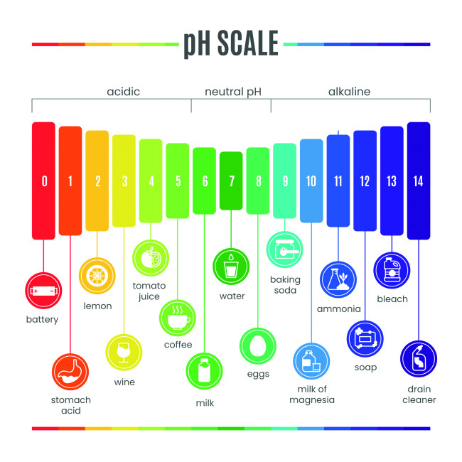
The pH is determined by the concentration of hydrogen ions (H+) present in the solution. When a substance dissolves in water, it can release hydrogen ions that determine the solution’s acidity. If these ions’ concentration is high, the pH will be low, indicating acidity. Conversely, if the hydrogen ion concentration is low, the pH will be high, indicating alkalinity.
As mentioned above, pH is an important parameter in many scientific and industrial fields. But it is also fundamental to human health, as various biological systems require an environment with a specific pH to function properly. pH measurement can be done using chemical indicators or electronic instruments called pH meters, which provide an accurate reading of the solution’s pH and are commonly used in chemistry laboratories and environmental analysis.
Probe for Measuring pH
In our project, we will use an electronic probe to measure pH (Figure 2). An electronic pH meter probe’s operation is based on electronic and chemical principles. It consists of a pH-sensitive glass electrode and a reference electrode. The former contains a special glass that reacts with hydrogen ions in the solution.
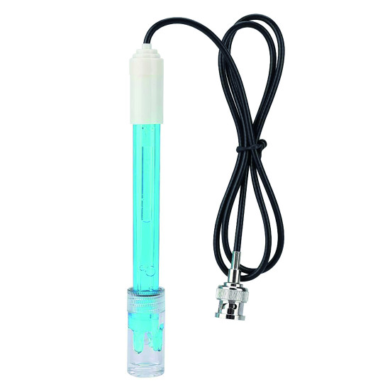
When the glass electrode is immersed in the solution, an electrical potential difference is created according to the solution’s pH. The reference electrode provides a stable reference point for pH measurement. Usually, a gel or salt solution reference electrode is used. The pH probe can detect the difference in electrical potential between the glass electrode and the reference electrode. This potential is converted into a pH value using an electronic circuit.
Before use, it is necessary to calibrate the instrument using known pH values (usually pH 4 and pH 7) to ensure measurement accuracy. Special care should be taken with the glass electrode, which should be stored in a specific solution and cleaned periodically to remove deposits that could affect measurements. The probe cannot be connected directly to our Arduino UNO R4 board, but rather the signal must be amplified and made readable by the microcontroller via a signal conditioning board (Figure 3).
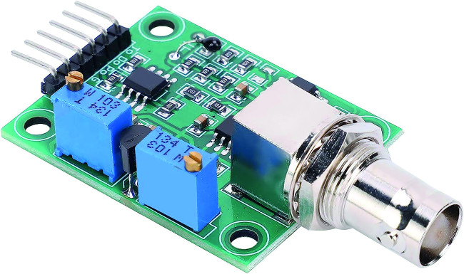
to the Arduino UNO R4. (Source: Elettronica In)
The pH probe is connected to the conditioning module through a BNC connector, which ensures a stable and reliable connection. The module has a voltage output pin that outputs a level proportional to the measured pH level. This pin can be connected to an analog input of a board, such as, in our case, Arduino UNO. For proper operation, the module must be supplied with a voltage of 5 VDC, and, given its low-power consumption (between 5 and 10 mA), we can supply it directly from the 5 V pin of our UNO R4 board. For proper operation, it is necessary to wait at least 60 seconds to get accurate readings.
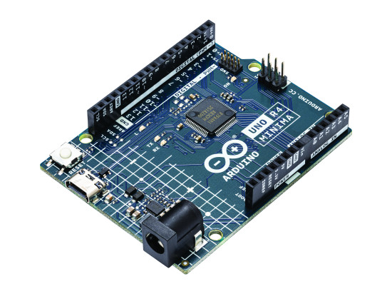
Arduino UNO R4 Minima
The fourth version of the Arduino UNO, the Arduino UNO R4 Minima, is a major step forward in the field of DIY and electronics (Figure 4). This new version houses a 32-bit Arm Cortex-M4 processor, providing more computing power and 16 times more memory than previous versions. Despite these improvements, the size and 5 V compatibility remain the same. This ensures a seamless transition for existing shields and projects, taking advantage of the extensive and unique ecosystem already created for the original Arduino UNO (Figure 5).
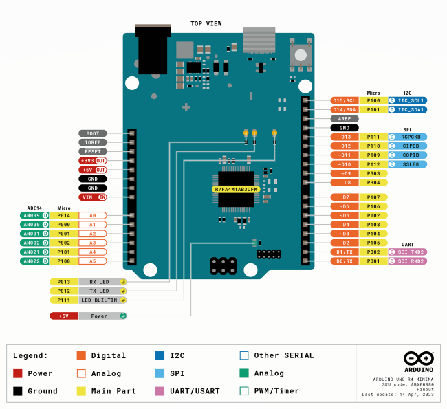
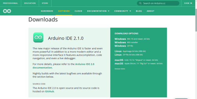
The new version also offers a faster clock, allowing it to perform more accurate calculations and handle complex and sophisticated designs. It also features a USB-C connector, which is a smaller, more powerful, and more durable standard than previous connectors. To use the Arduino UNO R4 Minima, you’ll need to install the UNO R4 Minima board package, which is part of the Arduino core for Renesas devices. To install it, you will need to have a version of the Arduino IDE, which you can download from the Arduino software page.
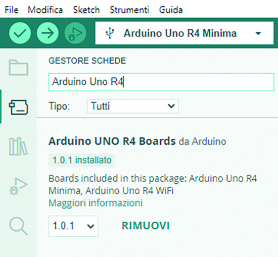
In this article, we will use the latest version of IDE 2 (Figure 6). To install the board package, open Board Manager from the menu on the left, search for UNO R4 Minima and install the latest version (or the desired version) (Figure 7). Now, connecting the board to the computer will create a virtual serial port that you can use for programming the Arduino.
Connections
In this project, we used several components to create a pH-detection system, as you can see in the wiring diagram (Figure 8). The main component, which is the probe that can detect pH, was connected to its conditioning circuit via a BNC connector. As mentioned earlier, this circuit takes its power directly from the Arduino UNO R4 board’s 5 V and GND pins. The pH-detection module’s pin P0 was connected to the Arduino board’s analog pin A0. This connection will allow the main board to read the pH values detected by the sensor.
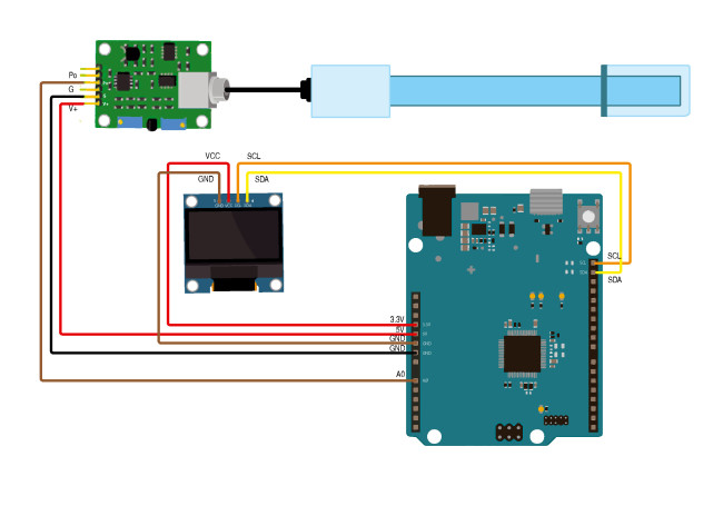
The OLED display used provides an I2C connection that allows, with only two wires besides power, to control the display. The display’s SDA and SCL pins are therefore connected to the Arduino R4 board’s SDA and SCL pins, while the power supply was taken from the 3.3 V and GND pins. This setup will allow us to measure pH using the probe and display the results on the OLED display. It is important to follow the given instructions carefully, as well as the connections shown in the wiring diagram, to ensure the system’s proper operation.
The Firmware
The code written for the Arduino UNO R4, downloadable at the Elektor Labs webpage of this project, allows us to read the pH sensor values and display them on the OLED. Let’s look at the code in detail. The first lines of code include the libraries needed for the program to work, in particular the Wire library for I2C and Adafruit’s Adafruit_GFX and Adafruit_SSD1306 libraries for managing the OLED display are included. Next, some constants and variables used in the program are defined (Listing 1).
unsigned long int avgValue; // stores the average value of the sensor feedbacks
float b;
int buf[10],temp;
#define SCREEN_WIDTH 128 // OLED screen width in pixels
#define SCREEN_HEIGHT 64 // OLED screen height in pixels
#define OLED_RESET -1 // reset pin (o -1 if the reset handling is shared)
Adafruit_SSD1306 display(SCREEN_WIDTH, SCREEN_HEIGHT, &Wire, OLED_RESET);
The setup() function is executed at startup and plays a crucial role in initializing the program (Listing 2). First, digital pin 13 is set as the output to control an LED. Next, serial communication through the serial monitor is initialized at a baud rate of 9600 baud. Next, serial communication via Serial Monitor is initialized at a baud rate of 9,600. After that, the program checks whether memory can be properly allocated for the SSD1306 OLED display. If the memory cannot be allocated, an error message is displayed and the program aborts.
{
pinMode(13,OUTPUT);
Serial.begin(9600);
Serial.println(“Ready”);
if(!display.begin(SSD1306_SWITCHCAPVCC, 0x3C))
{
Serial.println(F(“SSD1306 allocation failed”));
for(;;);
}
display.display();
delay(2);
display.clearDisplay();
display.clearDisplay();
display.setTextColor(WHITE);
display.setTextSize(2);
display.setCursor(10,5);
display.print(“PH Sensor”);
display.display();
delay(3000);
}
If, on the other hand, the display can be initialized correctly, a series of commands is executed to configure it. A short pause is initiated, then the display is cleared. The text size is set to 2, and the cursor is placed at display coordinates (10, 5). Next, the text “PH Sensor” is displayed by calling the display.display() function. A pause of three seconds is inserted to allow the user to read the message on the display before the program transfers to the loop() function. The loop() function is the heart of the Arduino sketch and is executed continuously after the setup phase (Listing 3).
{
for(int i=0;i<10;i++) //Get 10 sample values from the sensor to get a more accurate measurement
{
buf[i]=analogRead(SensorPin);
delay(10);
}
for(int i=0;i<9;i++) //Sort the analog values from smallest to largest
{
for(int j=i+1;j<10;j++)
{
if(buf[i]>buf[j])
{
temp=buf[i];
buf[i]=buf[j];
buf[j]=temp;
}
}
}
avgValue=0;
for(int i=2;i<8;i++) //take the average value of 6 center sample
avgValue+=buf[i];
float phValue=(float)avgValue*5.0/1024/6; //convert the analog into millivolt
phValue=3.5*phValue; //convert the millivolt into pH value
Serial.print(“ pH:”);
Serial.print(phValue,2);
Serial.println(“ “);
display.clearDisplay();
display.setTextSize(2);
display.setCursor(20,5);
display.println(“Ph Value”);
display.setTextSize(3);
display.setCursor(30,35);
display.print(phValue);
display.display();
digitalWrite(13, HIGH);
delay(800);
digitalWrite(13, LOW);
}
Within loop(), ten sample values are acquired from the pH sensor via analog pin 0. These values are then sorted in ascending order to calculate the middle six samples’ average value, for the purposes of noise reduction. This value is then converted to millivolts and then into the corresponding pH value. After that, the pH value is printed on the serial monitor with two decimal places of precision and displayed on the OLED.
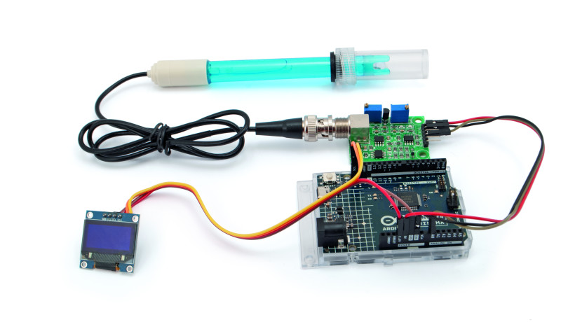
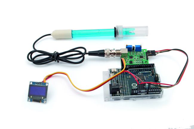
Finally, a light connected to digital pin 13 is turned on and off to provide visual feedback, and finally the program pauses for 800 ms before starting the loop over again, performing the same operations to acquire and calculate pH values. This loop repeats indefinitely as long as the Arduino remains powered. Figure 9 shows the completed, functional prototype.
Let’s Check the Waters
This article presented a pH measurement system using a dedicated sensor, the Arduino UNO R4 Minima board, and an OLED display. The system offers a versatile solution for accurately measuring a solution’s pH of a solution in various contexts, such as hydroponic farming, swimming pools, and aquaria. It’s an excellent starting point for adapting to your specific application.
About the Author

Boris Landoni is an electronics expert and a true enthusiast in the field. His dedication led him to become the managing director of Elettronica In, the most popular electronics magazine in Italy. He is also the curator of open-electronics.org, a platform dedicated to open-source projects that brings together enthusiasts and professionals. He is also the technical manager of Futura Elettronica, a leading company in supplying electronic components for the world of makers and professionals.
Discussion (13 comments)
pbaak 1 year ago
hmk 1 year ago
pbaak 1 year ago
EN0206289ID 1 year ago
Brian Tristam Williams 1 year ago
ABIZAR LAKDAWALLA 1 year ago
Brian Tristam Williams 1 year ago
pbaak 1 year ago
S.I ,Elektor 1 year ago
Thanks for notifying us about the broken link. Now it is working.
Regards,
S.I
Gunther Jordan 1 year ago
Content Director, Elektor 1 year ago
Gunther Jordan 1 year ago
What I learn: I can buy something.
What I do not learn: How to use the probe, how to measure, how to adjust or calibrate, how to store. What are the characteristics of the probe, is it a special probe, or can I use any other, How does the electronics work, what is the schematic, would it be possible to combine analogue(?) and digital parts on one board.
...would have a ton of more questions, would like to learn...
Nothing of this is provided in the article. It is only some ad...
Content Director, Elektor 1 year ago