
Industrial Counter for Print Count with Wireless Acknowledgement System [130557]
A digital counter is useful in Offices, malls, sports venues etc. Here we have designed an industrial counter that can be used with any printer or similar devices for counting paper or similar things. This device can be used for multiple applications of counting, just by changing the sensor input / counter input.
Introduction
A digital counter is useful in Offices, malls, sports venues etc. Here we have designed an industrial counter that can be used with any printer or similar devices for counting paper or similar things. This device can be used for multiple applications of counting, just by changing the sensor input / counter input.
We have implemented this device with a slot sensor which can be used to generate the counting pluses whenever a paper or similar thing passes through sensor slot. Due to this facility we named this device as an Industrial counter for print count. The count value is display using 5 big 7 segment displays to easyly readout of count value. Apart from this, the device also has a wireless acknowledgement system for tracking the couint values. This involves the Elektor GSM BOB module 140257, which sends and receives the status and command through SMS via valid mobile network.
Counting the paper from the printer helps to maximize the efficiency and the effectiveness of utilization of printers and sales potential of an organization. Wireless GSM connectivity provides functionality for getting information about the counts through SMS.
Features
- Fast, easy to install and access with any printer.
- Improves consumer relationship.
- Enhance creditability
- Feedbacks and reviews are easily tracked via SMS using a valid mobile network.
- Cost-effective
- Maximum count value is 99999.
- Manual Edit option for display with edit lock
- Operates on 9VDC /1A power supply
Hardware connectors
- K1: Connector on PCB 1 for connecting with PCB 2
- K2: Corresponding Connector for K1 of PCB 1 on PCB 2
- K3: Connector on PCB 1 for connecting with PCB 2
- K4: Corresponding Connector for K3 of PCB 1 on PCB 2
- K5: Manual edit connector on PCB 2 (Optional for remote use)
- K6: Power connector on PCB 2
- K7: Connector for slot sensor / paper out sensor of printer
Circuit Description
The circuit is divided in to two main sections one is Display Board and another is Control Board
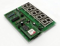
Display Board
This board is populated with 5 big (38.1mm) 7segment displays along with push buttons and interfacing connectors for connecting the display board to the control board. By using 5 digits of 7segment the device enables a maximum count value of 99999. Whenever the count value reaches 99999 the display is reset to 00000 and again the counting starts and so on…
The pushbutton S3 (PORTD.6 pin of IC3) is used to reset the count value, pushbutton S2 (PORTD.5 pin of IC3) is used select the digit to be edited and S1 (PORTD.4 pin of IC3) is used to increment the individual digit count from 0-9 for setting the count value. The push button S2 and S3 operate only if the EDIT mode is enabled which can be set by connecting the jumper J1 on the control board. The 7 segment displays used are of common anode type and are driven by a 9VDC using the driver section on control board. Connector K4 and K2 connects the display board to the control board.
Control Board
This board has many functions and holds majority of the components. This board is powered up by a 9VDC through connector K6. The 9VDC is further converted into a 5VDC for other circuitry by using IC1 MC7805 which is further monitored by the fail safe circuitry using IC2 TLC372. The output of IC2 is dependent on the comparison between the supply voltage set using the voltage divider R22, R23 and R24, R25. Any drop in the supply voltage causes high output from IC2 which is connected to MCU IC3 at portD.2 pin which is used as a fail safe interrupt. This interrupt forces the MCU to save the last count value into MCU’s inbuilt memory. This function is required to obtain the last count value for device whenever the user switches OFF and ON the device or any power failure.
The control board also holds the MCU section, 7Segment driver section, GSM BOB interfacing section, Sensor input section and manual edit option section.
MCU Section
This section is build around IC3 ATMEGA8-16PU microcontroller and performs all the main functions responsible for controlling and updating the display as per the inputs from the sensor, edit options, and GSM BOB signals. The Microcontroller is interfaced with an UART as an internal peripheral to communicate with the GSM Modem.
7-Segment Driver
This section operates on a 9VDC and drives the 7-segment display on the Display board with inputs from MCU IC3. Anodes of all the segments are driven by pairs of Transistors BC327 and BC548 for each display. There are total 5 pairs of transistors used for this (from T8 to T12 and T13 to T17).
The Displays are multiplexed and hence the same segments of each display are connected together to make one connection for a single segment, hence each common pin is driven by a single transistor BC517. Transistor T1 to T7 is used to drive each common segment of display.
GSM BOB interfacing section
This is used as an acknowledgement function between the device and the user. Whenever the count value reaches the threshold value then the default number set receives a SMS from the GSM Modem which contains the print count information. Also the display can be Reset and edited using the GSM Modem.
The control board is provided with a connector MOD1 for easy mounting and interfacing of Elektor’s GSM BOB with the device.
Procedure for using GSM functionality
- SMS needs to be sent to the SIM number of the card inserted into the GSM BOB which will in turn reply via SMS(NOTE: All the SMS’s will be charged as per service provider standard charges).
- When the GSM module sends or receives an SMS the seven segment Display flickers twice.
- To set default number to receive the reply from the GSM BOB:-
- SMS text - DEFAULT
- This message should be send from the number to be set as default number. this is for getting auto reply from module about threshold value reach
- As a reply, the GSM BOB sends the current count value via SMS which also indicates that the command sent was successfully processed.
- SMS text - DEFAULT
- To get the current count value displayed
- SMS text – STATUS
- This message can be send from any number and the module will reply the count value to the same number.
- SMS text – STATUS
- To reset the count value to 00000
- SMS text – RESET
- This message can be send from any number and the module will reset the count value to 00000.
- As a reply, the GSM BOB sends count = 0 via SMS to the same number.
- SMS text – RESET
- To edit thee count value
- SMS text – EDIT:<value>
- This message can be send from any number and the module will set the count value to the value send via SMS.
- As a reply, the GSM BOB sends the set count value via SMS to the same number.
- SMS text – EDIT:<value>
- To set the threshold value
- SMS text – THRESH:<value>
- This message can be send from any number and the module will set the threshold value to the value send via SMS.
- The threshold value can range from 00001 - 99999
- When the threshold value is reached the GSM BOB sends a SMS to the default number set.
- For example: if the threshold value is set to 100 then after every 100 counts the GSM BOB will send an SMS to the default number.
- SMS text – THRESH:<value>
Sensor input section
The sensor input can be connected through connector K7 to the control board. The digital signal pulses can be connected to this connector for counting. 0 to 3.3V or 0 to 5V pulses can be connected to K7. The connector having +5V supply for sensor and pulse input as input for control board. Hear slot sensor is used to generate the pulses which externally connected to K7 to the IC4 OP07. IC4 matches the 3.3V /5V signal level to MCU input level. This pulses are send to MCU IC3 for counting.
Manual EDIT option
This section enables the use of S2 and S3 switches on Display board for editing display count when required. Also connector K5 can be used to connect extra two keys for editing display from wired remote place near by device. Jumper J1 is used to enable the EDIT function by shorting its two pins.
Procedure to use manual edit option
- Connect the slot sensor on connector K7, if slot sensor not connected the manual edit mode will not work.
- Short jumper J1
- On pressing switch S2 the first seven segment from the right (LD1) starts blinking its current value which indicates that its value can be incremented by pressing switch S1.
- After adjusting the desired value of the seven segments, Press switch S2 to save the value and to select the next seven segments for edit that is, LD2 starts blinking its current value.
- Repeat the above steps until the value for the last seven segment that is, LD5 is set. After all the seven segment values are set the display becomes stable and begins to increment the count from the set value.
Procedure for assembling and testing of prototype
- Solder and assemble all the components according to schematic of PCB1 and PCB2.
- Connect the Elektor’s GSM BOB to connector MOD1 on PCB 2
- Short the connector K1 (power ON connector for GSM module) on the GSM BOB module with a 2 way jumper.
- Insert a valid working SIM card in SIM1 slot of GSM BOB.
- Connect a 9V dc power supply to connector K6
- Connect the slot sensor to connector K7
- Power up the unit
- On power up Display starts to initialize from right to left. During initialization you will see that the display displays digits from 1 - 5 from right to left once slowly and twice rapidly after which it displays the last saved value of count.
- There is no separate “SAVE” button to save the value of count as the circuit will automatically save the count value before the device powers off.
- Switch S3 can be used to reset the count value to 00000(Display will not reset if slot sensor is not connected).
- Switches S2 (used to select a digit to be edited) and S1 (to increment the value of the digit to be edited) can be used to manually edit the value of count to be displayed. This can be done only after shorting jumper J1 (which is edit lock).
- If jumper J1 is open then edit option is disabled.
- You can also remotely connect switches to connector K5 in order to edit the count value displayed
- Now you can check the device functionality by swiping paper (or any obstacle).the count value must increment by one on each swipe.
- The delay between two swipes is 200 ms, this means that count/second is 5.
Steps for testing the GSM module (if required)
- Connect the Elektor GSM BOM module to MOD1 connector on the control board
- Connect the 9VDC power supply via connector K6.
- Check the LED1 status on the BOM module, it should glow. The LED1 represents Power ON and LED2 indicates Module working.
- The SIM900A module comes with a boot loader, so once the GSM modem is powered up the LED2 starts to blink. The blinking status indicates that the GSM modem is start up.
- Short the jumper J1 for 4-5 seconds and remove it. This activates the module’s power ON key.
- Insert a SIM Card (SIM identification module) into the connector SIM1.
- Use an USB to serial BOB module to test GSM BOB.
- Reverse the connections between GSM Modem and USB to serial converter BOB. Connect TXD pin of the USB TO SERIAL BOB to the RXD pin of the GSM MODEM and vice versa that is, the RXD pin of the USB TO SERIAL BOB to the TXD pin of the GSM MODEM.
- Make the common GND connection between the USB to serial converter and GSM modem.
- Check the GSM modem by making a call to the SIM number which is inserted into the GSM Modem.
- Open the hyper terminal with a standard default BUAD RATE of 9600.
- Use Necessary standard AT Commands to Test the GSM modem from the hyper terminal and for more information about testing commands refer 140257-1_GSM BOB article.
Want to build a project?
Bring your design to life with the Elektor PCB Service, powered by Eurocircuits. Upload the project files and order professionally manufactured PCBs or assembled boards through a proven European production platform.
Supporting KiCad, Eagle, Gerber, and ODB++ formats, the service is suitable for everything from prototypes and validation builds to series production and volume manufacturing.
Made in Europe. Fast. Reliable. Professional.
Discussion (1 comment)