
Android style capacitive sensing pattern lock [120579]
Capacitive sensing projects are rarely seen in the pages of Elektor. However, with a few design tips and some code lines, you can add capacitive touch technology to your projects to without pain!
Capacitive sensing projects are rarely seen in the pages of Elektor. However, with a few design tips and some code lines, you can add capacitive touch technology to your projects to without pain!
Published in issue 436, April 2013
Order from Elektor
PCB, bare, 120579-1
ATtiny88-AU, programmed, 120579-41
After a previous successful work with this technology, I'd like to share this with all of you by designing a didactical project, for fun, or for the many uses you will find to it.
The goal of this project is to develop a security lock pad inspired by the famous "Pattern unlock screen" which can be seen on Android Phones. For those who do not see what I mean, the picture should help. It consists of drawing a scheme by sliding the finger on 9 dots. The system unlocks only if the pattern (or dot sequence) is correct (identical to previously recorded one).
This kind of lock presents many advantages compared to classical digit locks :
- A scheme is easier to memorize than a digit sequence
- Capacitive sensing is waterproof by conception, which is tricky to obtain with mechanical keys
- Keypad is backlighted to be used in dark or daylight
- A capacitive pad costs nothing more than the microcontroller. Don't care anymore about keys, caps, springs,...
- A capacitive pad has unlimited life compared to mechanical ones
- and... unlocking your gate or your personal computer simply by drawing with your finger is sooo much more funny than simply pressing a button ;-)
Now let's give some precision about the functionnalities :
- Heart of the system is based on an Atmel microcontroller embedding their QTouch Library which gives the ability to almost every µC to control capacitive keys, a wheel or a slider with practically no supplementary hardware
- The system is able to recognize 2 previsouly recorded schemes. Each of them activates a relay output.
- The capacitive panel is made of a 3mm thick plexiglas of about 60x60mm. The material is transluscent white; this completely hides capacitive board while diffusing leds light on a nice round spot. The choice of the sensing material is very important in capacitive sensing designs. This one is fairly easy to find and cheap.
- The capacitive panel consists of a 3x3 capacitive buttons matrix. Each of them is backlighted.
- Leds are driven by a specialized led driver from Maxim which gives the ability to control each individual current on an I²C bus. Great to implement fading effects while touching the panel...
- The board is powered by two alkaline 1.5V batteries. A great effort is made on hardware and software to minimize power consumption, especially in idle mode. The choice of a battery powered system is a bit more tricky but greatly simplifies integration in many applications (Computer power button, garage door...)
- Two hardware hidden contacts are provided to reset memorized patterns and learn new ones.
Well, I think that's all I can say for the moment. I hope you will be interested in this application and will help me to go on with this design. Do not hesitate to leave your comments, improvements, suggestions on this project !
Edit 31/08/2012 : Power Supply architecture
As I told you, I'm back after a few holidays (wedding holidays...).
I have thought about the design a bit further. I want to use blue or true green leds which are far more great looking than traditional ones. However, those chips present a direct forward voltage higher, around 3.7V. I absolutely want to keep the 2 battery power supply (which only gives 3.0V) for current consumption reasons while on sleep mode. So, the main board will embed a voltage booster to generate 5V from 3V. Of course, it will only be activated on demand, when leds need to be lit. I've choosed to use a TPS61070 from TI which has a shutdown current of only 0.5µA ! It also has a feature called "True Shutdown". Without this, 5V could never be really cut off.
With leds now powered with 5V, the maxim driver (MAX6956) also needs to be 5V powered... This leads to a new problem : How can an I²C bus be shared between 3V devices (microcontroller) and 5V ones ? I've resolved this issue by selecting the SPI version (MAX6957) and adding voltage level translators (SN74LVC1G07). Those buffers have a 5V tolerant open-drain output, even when powered from 3V. They will be powered by an output from the microcontroller (the same output which will be used to enable the boost regulator), to completely cut them off during sleep mode.
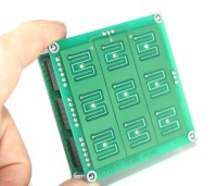
I have also worked on Capacitive Printed Circuit Board. The schematics of this board can not be simpler. It only contains 9 capacitive sensors (printed shape), 9 leds and 9 capacitors. I just spent a little time to define the best shape for the sensors... That should work... I will post the entire schematics next time, at the moment it won't give useful information. However, just have a look on this board's layout !
Edit 05/09/2012 : Schematics available
After a few hours of work, the revision A si available in the section "schematics". I finally used the I²C version of the MAX driver, the I²C bus is now shifted with 4 N-channel Mosfets, wich are cheaper than my previous idea with open drain buffers on a SPI bus.
The project is cut in 2 boards. Capacitive electrodes and backlight leds are located on the first one (page 1 of the schematics), while microcontroller and peripherals are on a stacked board (Pages 2 and 3).
On page 3, you will notice how capacitive hardware, made of R8-10, R14-R16 and C22-24 is simple... The layout has to follow a few guidelines but additional parts are reduced.
The layout is 90% finished. I just have to check all the layers and generate Gerber files... Will come soon !
Edit 07/09/2012 : Layout available
The board's layout is available in the PCB section. PDF shows the two boards attached together to reduce tooling fees while manufacturing. Dimensions are 70*143mm, double layer. The two boards will be stacked with male header and M3 screws after soldering. The two AAA battery case is located on the bottom of the 'intelligent' board.
Software conception
I've started to think to the software architecture. I successfully managed to include the QTouch library in a few lines software, sounds great ! :-) I've drawn the main state machine which will drive the microcontroller. You''l find it under the 'Photos' section because Software can only be uploaded as zip file.
Edit 21/09/2012 : Software written
While waiting for receiving the PCBs, I've just finshed to write the C software, which you can view in the appropriate section. The code is written, compiles with no error nor warning, but is not tested at all ! I've also updated the state machine diagram with a few minor changes.
The main() function is sliced in many short states which will - I hope - help readers to understand the software.
Map file gives 5459 bytes of CODE memory and 371 bytes of DATA memory, which perfectly fits in an ATtiny88. I first wanted to use an ATtiny48 but the Touch Studio form Atmel doesn't offers this choice. That's strange because those chips are exactly the same (except memory size of course).
In this version, the software activates the recognized output for 500ms only, and then releases it. I've done this to simulate the power button of a computer but can easily be changed for a flip/flop action.
Edit 03/10/2012 : Soldering and testing
I finally received my PCB and soldered them. As you'll see in attached pictures, all parts are SMD. However, as density was not an issue, I chosed 1206 package wherever I could wich is quite easy to solder. The only difficult part for begginers is the MAX6956 SSOP package with a 0.65mm pitch. I'm used to soldering it with a relatively thick tip on my iron, and doing a big solder join covering all pins together. I then use soldering braid to remove excess solder.
The top board only supports capacitive electrodes, leds and their decoupling capacitor (mandatory). Leds are reverse mounted, with the lens going through PCB hole.
I take some pictures without plexiglass layer to show capacitive electrodes design, but it won't work without it. The plexiglass panel is made from "truLED WH72" available online at Plexiglas shop in 3mm thickness. This material is the most diffusing I've found and is able to spread the led light to a nice circular shape with a diameter of more than 10mm. The plexiglass will then be covered with an adhesive colored layer.
Capacitive sensing is -very- sensitive to mechanical changes on the electrodes. The dielectric panel shall be firmly fixed to PCB to avoid any false detection or "stuck" keys (even if a recalibration algorithm is used). Any air gap between PCB and panel will considerably destroy sensing gain. The easiest way to do this is to stick both layers together. I use 3M VHB tape which is a transparent adhesive tape of a few µm thick. However, a bonding with a thin layer of epoxy glue on all the surface will work well too. Just make sure to use transparent glue...
Now testing is in progress, capacitive sensing seems to work well but I didn't spend much time on it at the moment. More news coming soon !
Edit 03/10/2012 : Current consumption measurement
As a battery powered system, current draw in idle mode needs to be as small as possible. I was secretely expecting a few µA but with these values, a small error in design can quickly waste hundreds of them !
First, I have to detail the software wakeup mechanism. With no activity on touch panel, microcontroller spends most of his time sleeping. Before entering sleep mode, the watchdog is activated to generate an interrupt after 300ms. On interrupt, microcontroller wakes up, launches a capacitive acquisition, and checks if an event occured. If the user touches the panel at this moment, leds are lit up and softwares goes to run mode. Else, it goes back to sleep.
I measured current while in sleep mode with a precision multimeter. I found 5µA continuous, with short peaks of a few mA. I then measured the shape of these peaks by measuring voltage drop between the leads of a 100ohms resistor placed in series with the batteries. You'll find scope captures in photos section.
Peaks are 240mV high (2.4mA), and last for 12ms, repeated every 300ms, as expected...
The idle average current can then be calculated with :
I_idle = 5µ + 2.4m*12m/300m = 101µA.
That's a bit high, I was hoping capacitive measurements would last less... With this configuration, two 1000mAh alkaline AAA cells would provide power for about 10'000h (about 416 days).
To reduce power, an easy way is to increase watchdog period. The user will then have to put his finger longer on the touch panel before the system wakes up. A 1200ms period gives an average current of 29µA, which is far better.
Edit 16/10/2012 : Project completed ! Demonstration video available
Last development hours have been spent on fine tuning the software and capacitive key's parameters to have the smoother response without overdetecting fingers. All works great now, user is able to record two patterns by strapping two pins on startup. Of course, those pins will have to be hidden after programming to prevent unauthorized access. For maximum security, those pins could even be disabled with a special software after recording is done... The whole code is greatly documented, you should be able to adapt to your need without much pain.
The demonstration video is available at : http://youtu.be/2B2_u9JiIT8?hd=1
The watchdog is now set to 600ms to compromize between power consumption and reactivity on wake up. I found a startup option wich was set to add a 4.1ms delay between wake up and next instruction, for oscillator stability. I did not measure the new current waveform, but wake up time should, in theory, be reduced from 12ms to 7.9ms, giving an idle current of : I_idle = 5µ + 2.4m*7.9m/600m = 36.6µA.
Two standard alkaline AAA cells should provide energy for about 1100 days...
Schematics is updated to revision B, corresponding to actual manufactured PCB.
Edit 12/01/2013: Bonus Software !
My daughters (18 months and 3 years old) like playing with the PatternLock, but it does not reacts very friendly with her. After a few touches, it locks itself to protect against unauthorized access...
I've just customized the software just for her. By adding a small 8ohms loudspeaker in place of one output relay, I've transformed the PatternLock into a PatternPiano, able to play 9 tones when keys are touched !
Hope they'll enjoy it!
Edit 05/11/2013: Updated Software !
With the help of a German reader, Christian Peskov, I dived back in my software lines to make it compatible with Atmel Studio 6 which integrates a free C (GCC) compiler.
You'll find this new revision (rev. C) in the included files ! The complete project is also available (for free) from the article page.
Published in issue 436, April 2013
Order from Elektor
PCB, bare, 120579-1
ATtiny88-AU, programmed, 120579-41
Want to build a project?
Bring your design to life with the Elektor PCB Service, powered by Eurocircuits. Upload the project files and order professionally manufactured PCBs or assembled boards through a proven European production platform.
Supporting KiCad, Eagle, Gerber, and ODB++ formats, the service is suitable for everything from prototypes and validation builds to series production and volume manufacturing.
Made in Europe. Fast. Reliable. Professional.
Discussion (4 comments)