CNN-based intelligent bolt failure detection vehicle for railway system
A model bolt failure detection vehicle, whose core function is to detect the bolt failure with CNN-based image recognition algorithm, is designed in this project. A MAX78000 is used as the core controller in this project. Specifically, two main functions are undertaken by MAX78000 controller, i.e., detecting the bolt failure with the on-board camera by implementing the CNN-based recognition algorithm, and sending the control signal to the model vehicle which is controlled by an additional STC89C52 controlle
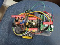
IntroductionA model vehicle-mounted bolt failure detection device is designed in this project. The project is motivated by the requirement for failure detection in railway system. High-speed rail roulette bearings occupy a pivotal position in equipment testing, and are usually the most vulnerable part of mechanical equipment. According to mechanical failure statistics, the proportion of rolling bearing failures in high-speed rail running accounts for 40% of mechanical failures. Therefore, it is of great significance to carry out fault diagnosis research on high-speed rail bearing bolts. It is usually difficult to check the large amount of bolts installed on the rail tracks or axles of the trains by the inspector one by one. Because of this, a failure detection device on the basis of image recognition algorithm benefits to the detection efficiency of the bolt failure. Moreover, the distance between successive bolts is constant. Therefore, the detection device can be equipped on the inspection vehicle to reduce labor intensity of the inspectors. In this project, a simplified model of inspection vehicle is designed on the basis of the requirements for bolt failure detection in railway system. The core controller of the model is MAX78000 and a CNN-based image recognition algorithm which can be accelerated by the mentioned controller is implemented to detect the failure of the bolts. The CNN algorithm tested 2000 images in the test set through the model obtained from 15000 training sets, and the recognition accuracy rate was over 95%, thus verifying the effectiveness of the model. Based on the fault detection vehicle of this project, the area and type of hardware and algorithm fault detection of the detection vehicle can be optimized, so that we can enrich the use scenarios and environment of the fault detection vehicle, liberate labor, and improve social efficiency. Framework of the projectThe core function of the project is detecting whether a bolt failure occurs at fixed points of the lane representing the rail track. Therefore, a model vehicle equipped with a MAX78000 controller runs along with the lane and stops at regular time intervals to detect the bolt failure. The detection algorithm is implemented at the fixed points. If the failure occurs, the vehicle stops and send an alarm signal (which is a red light in this project) until the failure is fixed. When the failure is removed, a certain button on the controller should be pressed and then the vehicle can move on to the next point. Otherwise, the vehicle runs to the next point directly. The framework of the mentioned function are shown in the images which can be found in the attachments. According to the analyzes above, two main parts can be divided in the project, i.e., the control algorithm of the model vehicle and the CNN-based failure detection algorithm. The detailed description are presented in the following chapters. Control method of the model vehicleIn this project, an additional STC89C52 is used to control the model vehicle in order to simplify the control process of the vehicle. A control signal is sent to STC89C52 controller from the output pin of MAX78000. If a high level is sent to STC89C52, the model vehicle can run along the lane. Otherwise, the vehicle holds its position. The detailed information of the model vehicle are listed as follows. 1. Body structure:(1)Power supply:Four 1.5V AA batteries connected in series to supply power to the MCU(2)MCU:Using 80C51 single-chip microcomputer as the control chip. STC89C52 is a low-power, high-performance CMOS 8-bit microcontroller produced by STC, with an 8K byte system programmable Flash memory. STC89C52 uses the classic MCS-51 core, but has made a lot of improvements to make the chip have functions that the traditional 51 single-chip microcomputer does not have. On a single chip, with a smart 8-bit CPU and in-system programmable Flash, STC89C52 provides a highly flexible and effective solution for many embedded control application systems.(3)Drive module:Use L289 as the drive module of the motor. The L298 is an integrated monolithic circuit in a 15- lead Multiwatt and PowerSO20 packages. It is a high voltage, high current dual full-bridge driver designed to accept standard TTL logic levels and drive inductive loads such as relays, solenoids, DC and stepping motors. Two enable inputs are provided to enable or disable the device independently of the input signals. The emitters of the lower transistors of each bridge are connected together and the corresponding external terminal can be used for the connection of an external sensing resistor. An additional supply input is provided so that the logic works at a lower voltage.(4)Detection device:Reflective photodetector RPR220.The detection device RPR-220 is an integrated reflective photodetector. The transmitter is a gallium arsenide infrared light-emitting diode, and the receiver is a high-sensitivity, silicon planar phototransistor. Mainly used in game machines, copiers and office automation equipment. Features:1. Plastic lens to improve sensitivity; 2. Built-in visible light filter to reduce the influence of discrete light; 3. Small size and compact structure.(5)Other parts:Use acrylic board as the chassis of the trolley, and fix the module with screws, nuts, copper posts, etc. The motor can rotate forward or reverse. The motor drives two front wheels, and there is a free universal wheel at the rear of the trolley. 2. Circuit connection:The battery box leads out the neutral wire and the live wire to connect to the power supply of the MCU. The P1.0 pin of the MCU is connected to the MAX78000 and receives the control signal from the MAX78000. The VCC port and GND port of the MCU are respectively connected to the driving voltage port, GND port and high level port of L289. The P1.2-P1.5 pins are connected to the four input pins of L289 as the input of motor control signals. The P3.6 and P3.7 pins are connected to RPR220 to receive the signal from the infrared sensor. Fault identificationAiming at the feature loss of one-dimensional convolutional neural network when processing time-domain signals, we propose a bearing fault diagnosis method based on two-dimensional convolutional neural network. The collected data is converted into gray-scale images, the bearing fault features are self-extracted using convolutional neural network, and the fault features are input into the limit tree regression for training and testing, so as to realize the fault diagnosis of bearing bolts.Regarding the production of the data set, we collected a total of 15,000 pictures taken on-site for the training set, and a total of 2,000 pictures in the test set. The test analysis is carried out through the test set, and the accuracy of 95% can be achieved by using this model for bearing fault classification. Experimental results show that the model can effectively identify the types of faulty bearings and has good robustness. CNN diagnosis processThe flow chart of CNN-based algorithm is shown in the image which can be seen in the attachments. The CNN model mainly includes two parts: training the CNN model to extract the features of the faulty bearing; then, the 128-dimensional feature vector of the CNN fully connected layer is trained and tested to diagnose the bearing fault. The CNN diagnosis process is shown in the figure 2. The combination of the CNN fault recognition algorithm and the hardware part is that the car continuously calls the camera module to take pictures and judges. When the car detects that there are bolts in the image, it calls the CNN model for identification and judgment. When the output result shows that the bolt is faulty, it will notify you The trolley malfunctioned. ExperimentsThe hardware of the experiment consists of a model vehicle controlled by STC89C52 controller, the simulated high-speed rail wheel and its screws, and obstacle-free path of the car. The related settings of the model vehicle are shown in the submitted image which can be found in the attachments. Two screws are installed on the chassis, the conventional screw and the control screw. Adjust the size of the roulette picture according to the screw size and make the screw background. Set the two screws on one side of the trolley path at a certain distance, and wait for the trolley to pass by. The core code of this project is edited on Eclipse and MaximMicrosSDK.The results of the experiments are shown in the images which can be seen in the attachments.
Want to build a project?
Bring your design to life with the Elektor PCB Service, powered by Eurocircuits. Upload the project files and order professionally manufactured PCBs or assembled boards through a proven European production platform.
Supporting KiCad, Eagle, Gerber, and ODB++ formats, the service is suitable for everything from prototypes and validation builds to series production and volume manufacturing.
Elektor Magazine has been one of the leading sources of information on electronics for engineers, designers, start-ups and companies for 65 years. Our magazine is powered by an active community of electronics engineers – from students to professionals – who are passionate about designing and sharing innovative ideas.
For them, we publish hundreds of items a year, in formats such as articles, videos, webinars, and other learning formats. Our mission is to share knowledge in every possible way and inspire readers with the latest developments within the electrical engineering sector.
Thank you for your vote!
Leave further comments in the fields below.
Thank you for your vote!
If you wish to leave a comment with your rating, please first use the login below. If not, just close this window.

Discussion (0 comments)