Home Automation with XBee modules
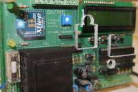
The goal of this domotica project is to create a wireless home automation project using ZigBee protocol with XBee modules as radio and Pic as microcontroller and Raspberry-Pi als controlling and logging inteligence.
- First stage is to construct a 4-channel light switch/Dimmer system. Containing a 4-channel triac dimmer/switch board, a controller for the dimmer board and a remote control for commanding all the nice.
- Second stage is a automated door for the chicken house to protect them agains nightly visits of the foxes.
- Thirth stage is an individual on/of swicht powered on 240V and so small it fits in a normal wall-switch-box And many many other things.....
I will be adding the developement of the project in separate contributions so that the the readability will bee better.
Contributions: (attention contributions in reverse order)
- 1.1. The triac dimmer/switch principe (17/05/2013)
- 1.2. The triac dimmer/switch Practical realization. (18/05/2013)
- 1.3. How a dimmer works (27/05/2013)
.
- 2.1. Zero-pass-detection (21/06/2013)
Comming soon:
- 2.2. Phase-control with the PIC-18
To be continued soon.....
Discussion (4 comments)
ON7AMI 11 years ago
Zero cross detection.
As we have to send an ignition pulse to the Triac to make it ‘close the switch’ and this on every half sine wave at exact the same time (see ‘The triac dimmer/switch principe’ in previous contribution), we have to detect the beginning of the (half)sine-wave. As the triac works in both positive and negative current direction, we need a signal on each zero-crossing of the sine wave.
So we can best use a full-wave rectification and then determine when the waveform reaches zero. To detect this point, we can use kind of a smith trigger circuit giving an output signal when the input drops below a certain level and the signal falls off when the input signal rises back above.
After some searching on the internet I came on the LM311 a single comparator which was ideal for this purpose. (http://www.fairchildsemi.com/ds/LM/LM311.pdf)
On the figure, ZC-fig-3-Sch.png you can see the construction of the circuit. I have chosen for a wave rectification from a symmetrical 2x9V transformer so I have a ground point that can be used, both for feeding the whole circuit and a signal for the zero-cross detection
In Figure ZC-Fig-1.bmp you see on Channel 2 (yellow) the rectified voltage on R5 (side diodes) and Channel 1 (green) shows the output pulse from the LM311 [Netsync]. On ZC-Fig-2.bmp you see an enlarged view on which you can see how precisely the rising edge of the pulse approached the zero-voltage within a few tenths of a degree.
This pulse will be used to control the interrupt from the PIC 18
Through the diode D3, we will also build the power voltage for the LM311 and the rest of the power supplies.
In the next article we dive into the PIC-18 software to see how we can make a software phase control on the leading edge.
zc-fig-2.PNG (3kb)
zc-fig-3-sch.png (5kb)
ON7AMI 11 years ago
How a triac dimmer works.
For those who want to refresh their knowledge about the working of a dimmer, there are very good articles on the internet explaining the fundamentals of a dimmer using a triac as a switching element.
One simple bud adequate one you’ll find here: http://home.howstuffworks.com/dimmer-switch.htm .
What we’re going to do is emulating the function to steer the gate of the triac with a microcontroller. To do so the microcontroller has to know the moment the mains sine wave crosses the zero-volt, then waiting a while and send out a pulse to put the triac in a conducting state.
In the next article I’ll describe the circuit to detect the zero-crossing of the mains.
ON7AMI 11 years ago
Bobbylebob 11 years ago
ON7AMI 11 years ago
Practical realization.
The practical realization of the dimmer circuit is in practice for times the principal circuit. The printed circuit is conceptualized so that each channel is one beside the other and that it is possible to cut the board in separate dimmers.
The circuit board is dimensioned as an euro board 160x100 mm so that each channel is 40x100mm. The connections for the steering pulses are at one side and the mains voltage connections at the other side.
Included in this contribution are:
Partlist:
img-2179.JPG (2445kb)
PCB in pdf (252kb)
Schematic in pdf (33kb)
ON7AMI 11 years ago
The dimmer
The dimmer can be used as a phase cutting dimmer or as a on/off switch. The has to be a galvanic isolation between the logic and the 240V. (The circuis should work on other voltages to but recalculation of the snubber and the R2/R3 may be required.)
Here by the principle schematic.
- On X2-1 the ground of the logic is connected and on X2-3 the pulse to control the triac.
- R1 and R5 are current reducing resistors to limit the current in the LED of the optocoupler IC1
- The (opto)triac of IC1 is controlling te gate of the triac T1
- Between X3-1 and x3-3 the mains (240V AC) is connected.
- The High Voltage capacitors C1 and C2 together with the choke L1 are reducing the radio interference on the line.
- The load (max 6A) is connected to X1-1 and X1-3
Next step will be a test setup of the dimmer.
dimmer-0.jpg (45kb)