
Precision adjustable currentsource with HC595 and Raspberry PICO RP2040
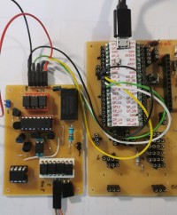
I use from the HC595 shift-register the first 5 bits as DAC and the three other for changing Uref from 2V to 800mV, changing from current to voltage-mode ( I-base / U-gate) and swifting between n-/ p-devices . The output is isolated from the controller (with cheap opto-coupler PC817) and from power with DC / DC converter. . The polarity of the output can be changed with Opto-relais like Omron G3VM61.
I will use the current-source for a transistor curve-tracer.
With this device it would be easy to test devices with different polarity like npn/pnp transistor or
n/p J-Fet or n/p Mos-Fet.
I have used only cheap parts, only the DC/DC 1W converter (5V to 30V isolated) is more expensive (and if you want to change the polarity with electronic switches you nead 5 mos-relais (2-3 €) each.
Description:
5 Input-pins for Gnd, ser.Data, Latch, Clock and + 5V (about 120mA),
Isolation Power with 1W DC/DC converter( different Layouts dependend from producer. and IsolationVoltage),
Isolation logic-inputs with opto-coupler (non inverting !, collector to + 5V !).
5V-Reference ( about 2k Ohm from +30V ), also used +5V for HC595 and Opamp (in currentsource).
Outputs from HC595 to Mosfets (inverters) for switching the resistors from DAC to Gnd (bit 0 to 4).
bit 5 to 7 for swiching Vref (currentsource) from 2V to 0.8V, switching fom base-current mode (bipolar) to gate-voltage mode (jFet/Mosfet) and switching polartity n/p devices.
The 4 Mos-Relais work like a dual-swich, changing outputs :
n-device: output 1 (base) more positive compared witch output 2 (emitter) .
p-device: output 1 (base) more negative compared witch output 2 (emitter) .
The currents go from 0µA, 50µA, 100µA ... to 1.55 mA (reference = 2.0V )
or from 0µA, 20µA, 40µA ... to 0.62 mA (reference = 0.8V )
or from 0µA, 10µA, 20µA ... to 0.31 mA (reference = 0.4V ) (in work!)
The voltages for J-/Mos-Fets are similar, depends from resistor at switch current to source.
Want to build a project?
Bring your design to life with the Elektor PCB Service, powered by Eurocircuits. Upload the project files and order professionally manufactured PCBs or assembled boards through a proven European production platform.
Supporting KiCad, Eagle, Gerber, and ODB++ formats, the service is suitable for everything from prototypes and validation builds to series production and volume manufacturing.
Made in Europe. Fast. Reliable. Professional.
Discussion (3 comments)