
Low Power Laser Interrupt Sensor, Again
This trail use counter is so different in design from my original submission that I decided to resubmit the project.
Laser Beam Interrupt Sensor
A couple of months ago, I submitted a project designed to use a laser beam interrupt technique for determining if/when someone had passed through a sensing zone. This was to be used as a hiking/biking trail-use counter. The electronics and code are so different from the initial project that I think it is more appropriate to start afresh.
This battery-operated device was designed to be installed at a trailhead and record the activity of hikers, bicyclists, etc. Because it is battery-operated, power consumption is a very important consideration. Typically, laser beam interrupt sensor arrangements are designed with the laser on continuously. However, even better quality five milliwatt red lasers consume about 20 mA. Using an 18650 battery (typically 2600-3000 mAh, with about 2000-2500 mAh usable) and not even taking into consideration additional electronics or the MCU, battery life would be less than one week, with power consumption of approximately 480 mAh per day. This was well outside design parameters.
However, we can take advantage of the fact that humans walk slowly; even bicycles are pretty slow in the context of detecting something or someone entering a detection zone. If a person were to walk through the sensing portal, they will potentially interrupt the laser for some time t. t will be related to the speed at which the person is walking and, for want of a better term, their diameter. So long as we test for beam interruption at any point during that time t, we can detect a transit. The situation is very similar to the Nyquist theorem for DSP sampling (a wave of frequency f will be correctly sampled, provided sampling takes place at 2f.) There is no requirement that the laser remain on continuously. We can pulse the laser, turning it on for a very short interval periodically. In practice, firing the laser 10 times per second for 100 µs produced a very reliable sensing arrangement. The laser is now on one millisecond out of every second, obviously a large drop in power consumption.
Sensing for beam interruption is coordinated with the firing of the laser. Coordination of sensing and firing of the laser is easily achieved by having the sensor and laser attached to the same MCU. Rather than a remote sensor, the beam is reflected back to its origin using an inexpensive mirror.
The second major source of power consumption is the MCU. Popular MCUs vary widely in their baseline power consumption, and selecting an MCU with an intrinsically low power requirement is an important part of the design process. Further savings can be realized by using various sleep modes or even external timers (see my weather station project). However, many deep sleep modes require considerable programming expertise to make optimum use of this feature.
My first prototype was based on an ESP-32 Sparkfun board. The deep sleep modes are well-exposed and well-documented. It was quite easy to write code that almost did what I wanted. What I had not anticipated, and learned only after quite a bit of testing, was that power-down and power-up times were unacceptably long, pretty much wiping out all the power savings. The ESP-32 MCU would be very good for a project where the MCU slept for minutes or hours. In that context, the power-down and power-up times would be an inconsequential fraction of the duty cycle. Not so for millisecond duty cycles.
I experimented with several other boards that supported deep sleep, including a nice SAMD21. However, turn-on and turn-off times were also unacceptably slow.
Ultimately, I changed tactics and switched to an intrinsically low-power board, the Sparkfun Artemis Nano. This brought my power consumption well within my design specifications. Note that I removed the power LED.
The laser module deserves some short discussion. Consumer OEM lasers typically consist of the light emitting diode--the laser LED--and a small regulator circuit to prevent thermal runaway. The power consumption that I measured among various lasers for the same specified mW light output varied widely. Measured power consumption raged from under 20 mA to over 50 mA. My strong suspicion is that this wide variability has more to do with the regulatory circuitry than the emitter itself. My final choice ran directly from 3.3V and consumed just under 20 mA. As I said in the BOM, the leads are a little delicate, but that can be overcome.
In addition to the laser, there are three other peripherals. First, there is the sensor. Initially, I used a small integrated light sensor/amplifier, the ISO203 photo sensor, widely available on Amazon and eBay. It had a slow response time and an unnecessarily high power consumption. I switched to a simple phototransistor which works just great.
The second peripheral is the real-time clock. Passage through the sensing zone is recorded as a simple timestamp. I use a DS 3231 module with a CR 2032 backup battery. In my initial efforts, this I2C device was queried each time I wrote to the SD card to record an interrupt. This was because the ESP–32 reset itself when waking up from sleep. In the current iteration, the power consumption of the Nano is so low that it does not need to be put to sleep. The real-time clock is queried once, during setup() and the MCU’s internal clock is synchronized to it. Subsequent timestamps are derived from the MCU’s RTC. Theoretically, since the RTC is queried only once during startup, a GPS module (powered only while in active use) could be substituted. It is very easy to extract UTC from the data sentence. GPS-derived time does not require a cellular signal or WiFi, which makes it suitable for a remote location. Just a thought, not necessarily a good one.
The third and final peripheral is the recording device. In this case, I use a low-capacity microSD card and a 3.3-volt microSD card reader. The bare-bones microSD card reader board that I used requires a good quality 3.3 V power source; 5 V will fry the SD card. Write-time is minimized by writing the UNIX time to the card rather than a full time and date phrase. Time can be decoded once the data card is retrieved from the trail monitor.
Earlier models of my project suffered from some electrical instability with unpredictable behavior of both the MCU and peripherals. Ultimately, I traced this to brownout events; I had relied on the voltage regulator on the MCU board to power all peripherals, thinking it would provide sufficient current. I now use a small buck/boost regulator from Pololu for the SD card. It’s a little expensive, but it is physically small and very efficient. It also has an enable pin, so I can shut off power to the board and the SD card reader when it is not in use. The Nano has a pretty robust voltage regulator, capable of putting out 600 mA. I might try going back to the MCU’s regulator. If I do so, I’ll post an update with the results.
Power switching is handled with logic-level MOSFETs. I use an N-channel MOSFET to switch power to the RTC module from the board’s 3.3 V regulator. The circuit results in a floating ground for the RTC module, which does not thrill me, but it also prevents power flow through data lines and pull-up resistors. The laser is also switched on and off using an N-channel MOSFET. The laser is also on a floating ground, but this is a more robust component and doesn’t worry me as much. I use a CEP8030L in a TO-225 package. It is a little bulky but has a very low ON internal resistance, in the order of milliohms. Any low internal resistance logic level power MOSFET can be used.
I set this arrangement up at the doorway of my work-from-home office. I am in and out of that room many times during the day. The battery, an 18650, was taken directly from the charger and put into service. In one week, I recharged the battery. It required 173 mAh to be fully recharged. I was happy. Note that I have taken to almost invariably putting a Schottky diode in line with my battery or other power supply to idiot-proof my circuit.
The current iteration also has two new features. It has an “aim” button which, when pressed momentarily, keeps the laser on for a prespecified period of time. This allows the user to undertake mechanical alignment of the laser, mirror, and sensor. Press detection could be implemented as an interrupt or by polling in the main loop. I chose the latter.
The second feature is the use of a config.txt file on the SD card. This is always a nice feature to incorporate in any project that uses an SD card or microSD card. Laser on time, interval time, and “aim” time are parameters that may warrant adjustment as the system is installed. Rather than hard-coding these numbers into the program, the setup() function can look for and open a config.txt file that is on the SD card. Device behavior can now be changed by simply changing that file rather than recompiling the program.
Two final points. The mechanical issues involved in deploying this contraption remain an issue. The phototransistor is a small target. Maintaining alignment of the sensor, laser, and mirror, as well as initial aiming, may require some ingenuity. The phototransistor also needs some light shielding to function optimally. Nonetheless, in certain use cases, this setup may be a really good solution.
The second point is the versatility of the idea. In addition to the loop() function that controls the laser and does the sensing, the other key function is DoSomethingUseful(). Think of this as a generic wrapper function. A laser interrupt event can trigger a wide range of responses depending on the contents of that function. An equally useful application, for example, might be a vehicle detector at the end of a long driveway, using a LoRa radio to signal the house that someone is coming.
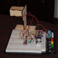
I have included the Arduino sketch, a bill of materials, a messy schematic, and pictures of my test setup. I don’t recommend wooden construction for deployment. However, I have found that when flat, thin materials are required for models or prototypes, designing and making panels from 1/8” plywood with LightBurn, a laser cutter, and glue is much, much faster than Sketchup and my 3D printer.
I have also included a second Arduino sketch that can be used to set the correct time on the DS3231. Put in the backup battery and compile and run the sketch once. The clock will be set at the time that the program was compiled, which should be within a minute of the correct time. If greater accuracy is required, it’s easy to query a GPS module or an NST time server, but the coding and wiring for these approaches are left as an exercise for the reader.
A couple of months ago, I submitted a project designed to use a laser beam interrupt technique for determining if/when someone had passed through a sensing zone. This was to be used as a hiking/biking trail-use counter. The electronics and code are so different from the initial project that I think it is more appropriate to start afresh.
This battery-operated device was designed to be installed at a trailhead and record the activity of hikers, bicyclists, etc. Because it is battery-operated, power consumption is a very important consideration. Typically, laser beam interrupt sensor arrangements are designed with the laser on continuously. However, even better quality five milliwatt red lasers consume about 20 mA. Using an 18650 battery (typically 2600-3000 mAh, with about 2000-2500 mAh usable) and not even taking into consideration additional electronics or the MCU, battery life would be less than one week, with power consumption of approximately 480 mAh per day. This was well outside design parameters.
However, we can take advantage of the fact that humans walk slowly; even bicycles are pretty slow in the context of detecting something or someone entering a detection zone. If a person were to walk through the sensing portal, they will potentially interrupt the laser for some time t. t will be related to the speed at which the person is walking and, for want of a better term, their diameter. So long as we test for beam interruption at any point during that time t, we can detect a transit. The situation is very similar to the Nyquist theorem for DSP sampling (a wave of frequency f will be correctly sampled, provided sampling takes place at 2f.) There is no requirement that the laser remain on continuously. We can pulse the laser, turning it on for a very short interval periodically. In practice, firing the laser 10 times per second for 100 µs produced a very reliable sensing arrangement. The laser is now on one millisecond out of every second, obviously a large drop in power consumption.
Sensing for beam interruption is coordinated with the firing of the laser. Coordination of sensing and firing of the laser is easily achieved by having the sensor and laser attached to the same MCU. Rather than a remote sensor, the beam is reflected back to its origin using an inexpensive mirror.
The second major source of power consumption is the MCU. Popular MCUs vary widely in their baseline power consumption, and selecting an MCU with an intrinsically low power requirement is an important part of the design process. Further savings can be realized by using various sleep modes or even external timers (see my weather station project). However, many deep sleep modes require considerable programming expertise to make optimum use of this feature.
My first prototype was based on an ESP-32 Sparkfun board. The deep sleep modes are well-exposed and well-documented. It was quite easy to write code that almost did what I wanted. What I had not anticipated, and learned only after quite a bit of testing, was that power-down and power-up times were unacceptably long, pretty much wiping out all the power savings. The ESP-32 MCU would be very good for a project where the MCU slept for minutes or hours. In that context, the power-down and power-up times would be an inconsequential fraction of the duty cycle. Not so for millisecond duty cycles.
I experimented with several other boards that supported deep sleep, including a nice SAMD21. However, turn-on and turn-off times were also unacceptably slow.
Ultimately, I changed tactics and switched to an intrinsically low-power board, the Sparkfun Artemis Nano. This brought my power consumption well within my design specifications. Note that I removed the power LED.
The laser module deserves some short discussion. Consumer OEM lasers typically consist of the light emitting diode--the laser LED--and a small regulator circuit to prevent thermal runaway. The power consumption that I measured among various lasers for the same specified mW light output varied widely. Measured power consumption raged from under 20 mA to over 50 mA. My strong suspicion is that this wide variability has more to do with the regulatory circuitry than the emitter itself. My final choice ran directly from 3.3V and consumed just under 20 mA. As I said in the BOM, the leads are a little delicate, but that can be overcome.
In addition to the laser, there are three other peripherals. First, there is the sensor. Initially, I used a small integrated light sensor/amplifier, the ISO203 photo sensor, widely available on Amazon and eBay. It had a slow response time and an unnecessarily high power consumption. I switched to a simple phototransistor which works just great.
The second peripheral is the real-time clock. Passage through the sensing zone is recorded as a simple timestamp. I use a DS 3231 module with a CR 2032 backup battery. In my initial efforts, this I2C device was queried each time I wrote to the SD card to record an interrupt. This was because the ESP–32 reset itself when waking up from sleep. In the current iteration, the power consumption of the Nano is so low that it does not need to be put to sleep. The real-time clock is queried once, during setup() and the MCU’s internal clock is synchronized to it. Subsequent timestamps are derived from the MCU’s RTC. Theoretically, since the RTC is queried only once during startup, a GPS module (powered only while in active use) could be substituted. It is very easy to extract UTC from the data sentence. GPS-derived time does not require a cellular signal or WiFi, which makes it suitable for a remote location. Just a thought, not necessarily a good one.
The third and final peripheral is the recording device. In this case, I use a low-capacity microSD card and a 3.3-volt microSD card reader. The bare-bones microSD card reader board that I used requires a good quality 3.3 V power source; 5 V will fry the SD card. Write-time is minimized by writing the UNIX time to the card rather than a full time and date phrase. Time can be decoded once the data card is retrieved from the trail monitor.
Earlier models of my project suffered from some electrical instability with unpredictable behavior of both the MCU and peripherals. Ultimately, I traced this to brownout events; I had relied on the voltage regulator on the MCU board to power all peripherals, thinking it would provide sufficient current. I now use a small buck/boost regulator from Pololu for the SD card. It’s a little expensive, but it is physically small and very efficient. It also has an enable pin, so I can shut off power to the board and the SD card reader when it is not in use. The Nano has a pretty robust voltage regulator, capable of putting out 600 mA. I might try going back to the MCU’s regulator. If I do so, I’ll post an update with the results.
Power switching is handled with logic-level MOSFETs. I use an N-channel MOSFET to switch power to the RTC module from the board’s 3.3 V regulator. The circuit results in a floating ground for the RTC module, which does not thrill me, but it also prevents power flow through data lines and pull-up resistors. The laser is also switched on and off using an N-channel MOSFET. The laser is also on a floating ground, but this is a more robust component and doesn’t worry me as much. I use a CEP8030L in a TO-225 package. It is a little bulky but has a very low ON internal resistance, in the order of milliohms. Any low internal resistance logic level power MOSFET can be used.
I set this arrangement up at the doorway of my work-from-home office. I am in and out of that room many times during the day. The battery, an 18650, was taken directly from the charger and put into service. In one week, I recharged the battery. It required 173 mAh to be fully recharged. I was happy. Note that I have taken to almost invariably putting a Schottky diode in line with my battery or other power supply to idiot-proof my circuit.
The current iteration also has two new features. It has an “aim” button which, when pressed momentarily, keeps the laser on for a prespecified period of time. This allows the user to undertake mechanical alignment of the laser, mirror, and sensor. Press detection could be implemented as an interrupt or by polling in the main loop. I chose the latter.
The second feature is the use of a config.txt file on the SD card. This is always a nice feature to incorporate in any project that uses an SD card or microSD card. Laser on time, interval time, and “aim” time are parameters that may warrant adjustment as the system is installed. Rather than hard-coding these numbers into the program, the setup() function can look for and open a config.txt file that is on the SD card. Device behavior can now be changed by simply changing that file rather than recompiling the program.
Two final points. The mechanical issues involved in deploying this contraption remain an issue. The phototransistor is a small target. Maintaining alignment of the sensor, laser, and mirror, as well as initial aiming, may require some ingenuity. The phototransistor also needs some light shielding to function optimally. Nonetheless, in certain use cases, this setup may be a really good solution.
The second point is the versatility of the idea. In addition to the loop() function that controls the laser and does the sensing, the other key function is DoSomethingUseful(). Think of this as a generic wrapper function. A laser interrupt event can trigger a wide range of responses depending on the contents of that function. An equally useful application, for example, might be a vehicle detector at the end of a long driveway, using a LoRa radio to signal the house that someone is coming.
I have included the Arduino sketch, a bill of materials, a messy schematic, and pictures of my test setup. I don’t recommend wooden construction for deployment. However, I have found that when flat, thin materials are required for models or prototypes, designing and making panels from 1/8” plywood with LightBurn, a laser cutter, and glue is much, much faster than Sketchup and my 3D printer.
I have also included a second Arduino sketch that can be used to set the correct time on the DS3231. Put in the backup battery and compile and run the sketch once. The clock will be set at the time that the program was compiled, which should be within a minute of the correct time. If greater accuracy is required, it’s easy to query a GPS module or an NST time server, but the coding and wiring for these approaches are left as an exercise for the reader.
Want to build a project?
Bring your design to life with the Elektor PCB Service, powered by Eurocircuits. Upload the project files and order professionally manufactured PCBs or assembled boards through a proven European production platform.
Supporting KiCad, Eagle, Gerber, and ODB++ formats, the service is suitable for everything from prototypes and validation builds to series production and volume manufacturing.
Made in Europe. Fast. Reliable. Professional.
Discussion (0 comments)