
RGBdigit clock [160100]
A very colourful clock, synchronised via Wi-Fi, With an optional BME280 eBoB sensor board it will also display temperature, humidity and air pressure.
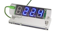
What do you do when you want to design ‘something’ with a vintage or modern display? A clock of course, and this is our first design with RGBDigits: multi-colour 7-segment displays. With a BME280 breakout board attached it will also display temperature, humidity and air pressure. The clock is controlled by an ESP12 module, which makes it possible to synchronise the clock with an internet time server, change the clock settings from any mobile device or computer in the network, or transmit sensor data via Wi-Fi.
RGBDigits are manufactured by a Dutch company with the same name. Every display contains eight 5050 RGB NeoPixel LEDs (seven segments + decimal point) with integrated driver chips, which allow the user to control colour and brightness of every segment/DP individually via a 3-wire bus (VCC, GND an DATA). Up to 10 displays can be daisy chained via their DATA IN and DATA OUT pins.
Each primary colour LED of a NeoPixel can be set to 256 levels of brightness, resulting in 256 x 256 x 256 = 16777216 colours for every segment/DP.
Schematic
The clock is 5V powered via micro USB connector K1. The power supply is protected by 2A PTC resettable fuse F1, Schottky diode D1 serves as reverse polarity protection. IC1 is the main 3.3V voltage regulator, IC6 is the 3.3V supply for the Qtouch touch sensors IC4 and IC5 (separated supply to prevent interference).
The two touch sensors Button0 and Button1 are used to control the display modes of the clock. S1 and S2 are only used for resetting the clock and flashing of the firmware.
IC2 serves as uni-directional level shifter between the 3.3V at the ESP-12E side and the V+ (approx. 4.5V) power supply of the displays.
EEPROM IC3 is used to preserve the clock settings after power off.
A 3.3V FTDI-cable (or other 3.3V USB UART) can be connected to K2 to flash the ESP-12E module, it can also be used for debugging applications.
A BME280 BoB (160109-1) can be connected to K4. The clock will run without it, but of course there will be no sensor data available. An onboard BME280 was no option, heat from the displays will influence the data.
LDR R1 is used to dim the displays in the dark.
K3 makes the 3.3V power and three general purpose I/O pins of the ESP13E accessible for your own developments c.q. future expansions.
Flashing the sketch
The ESP12E Wi-Fi module (which contains an ESP8266) is supported in the Arduino IDE.
add the ESP8266 (NodeMCU). Instructions on how to add the ESP8266 (NodeMCU) can be found at ), follow the steps described there before you can proceed. Unpack the ZIP-file to an Arduino sketch folder on your hard drive, ensure that subfolder DATA (containing the ESP12’s webpage) is preserved in this folder!
Note: if the compiler exits with an error, this is probably caused by one or more missing Arduino libraries. The compiler will report the name of the first missing library, but you can also check if all libraries used in the INCLUDE directives in the “esp8266_rgb_clock” sketch are installed in your Arduino IDE before you start the compiler.
Uploading the clock’s webpages
All settings of the clock can be controlled via Wi-Fi. The initial connection must be made via the ESP8266’s Access Point (AP). Connect your smartphone/tablet/laptop (or PC, if it has a direct Wi-Fi connection) to the open network called “RGB clock” that will appear in the list of available Wi-Fi networks after flashing the clock’s firmware in the previous step. However, first the clock’s webpages must be uploaded to the ESP8266 before you get easy access to the settings of the clock.
On https://github.com/esp8266/Arduino/blob/master/doc/filesystem.md, under ‘Uploading files to the file system’ you’ll find instructions how to do this:
Now the fun starts J Connect to the “RGB Clock” Wi-Fi network, open a browser and connect to 192.168.4.1:81. In the menu (top left corner) select “Wi-Fi settings” and enter the SSID and password of your wireless network. The clock will use this network to connect to the time server (NTP) to synchronise, and send sensor data to the server at Sparkfun (will be discussed later). In the sketch "time.nist.gov" is defined as NTP-server for our clock.
Note:
Every computer with access to your Wi-Fi router can now access the clock to change its settings. Simply type “clock.local:81” in the address bar of a browser to get access to the clock’s webpages.
1 http://www.instructables.com/id/Quick-Start-to-Nodemcu-ESP8266-on-Arduino-IDE/.
BOM 160100-1 RGBdigit clock
Resistor
R1 = LDR NSL-19M51
R2,R3,R4,R5,R6,R8,R9,R10,R11,R12 = 10 kΩ, thick film, 5%, 0.1W, 150V
R7 = 1 kΩ, thick film, 5%, 0.1W, 150V
Capacitor
C1,C5,C6,C7,C10,C11,C13 = 100 nF, 50 V, X7R, 0805
C2,C4,C9 = 10uF, 10V, tantalum 1206
C3,C15,C16 = 1 µF, 50 V, X5R, 0805
C8 = 100 µF, 16 V, 2312
C12,C14 = 10 nF, 50 V, X7R, 0805
Semiconductor
D1 = MBRS540, 40 V, 5 A, Vf=550 mV @ If=5 A
LED1,LED2,LED3,LED4 = 7-segment RGB-display
IC1 = LD1117S33TR, LDO, 3.3 V, 800mA
IC2 = 74LVC1T45GW transceiver 1.2V to 5.5V
IC3 = I2C EEPROM 8K x 8 bit 24LC64T-I/OT
IC4,IC5 = Qtouch Touch Sensor AT42QT1010-TSHR
IC6 = MCP1700T-3302E/TT, LDO, 3.3V, 0.25A
Other
F1 = PTC resettable fuse 2A MF-SMDF200-2 (Bourns)
K1 = Micro USB type B receptacle, bottom mount
K2 = 6-way SIL pinheader, 100mil , angled
K3 = 5-way SIL pinheader, 100mil , angled
K4 = 4-way SIL pinheader, 100mil, straight
K5 = 2-way SIL pinheader, 100mil , angled
MOD1 = ESP8266-12F
S1 = Tactile switch
PCB 160100-1 v2.2
RGBDigits are manufactured by a Dutch company with the same name. Every display contains eight 5050 RGB NeoPixel LEDs (seven segments + decimal point) with integrated driver chips, which allow the user to control colour and brightness of every segment/DP individually via a 3-wire bus (VCC, GND an DATA). Up to 10 displays can be daisy chained via their DATA IN and DATA OUT pins.
Each primary colour LED of a NeoPixel can be set to 256 levels of brightness, resulting in 256 x 256 x 256 = 16777216 colours for every segment/DP.
Schematic
The clock is 5V powered via micro USB connector K1. The power supply is protected by 2A PTC resettable fuse F1, Schottky diode D1 serves as reverse polarity protection. IC1 is the main 3.3V voltage regulator, IC6 is the 3.3V supply for the Qtouch touch sensors IC4 and IC5 (separated supply to prevent interference).
The two touch sensors Button0 and Button1 are used to control the display modes of the clock. S1 and S2 are only used for resetting the clock and flashing of the firmware.
IC2 serves as uni-directional level shifter between the 3.3V at the ESP-12E side and the V+ (approx. 4.5V) power supply of the displays.
EEPROM IC3 is used to preserve the clock settings after power off.
A 3.3V FTDI-cable (or other 3.3V USB UART) can be connected to K2 to flash the ESP-12E module, it can also be used for debugging applications.
A BME280 BoB (160109-1) can be connected to K4. The clock will run without it, but of course there will be no sensor data available. An onboard BME280 was no option, heat from the displays will influence the data.
LDR R1 is used to dim the displays in the dark.
K3 makes the 3.3V power and three general purpose I/O pins of the ESP13E accessible for your own developments c.q. future expansions.
Flashing the sketch
The ESP12E Wi-Fi module (which contains an ESP8266) is supported in the Arduino IDE.
add the ESP8266 (NodeMCU). Instructions on how to add the ESP8266 (NodeMCU) can be found at ), follow the steps described there before you can proceed. Unpack the ZIP-file to an Arduino sketch folder on your hard drive, ensure that subfolder DATA (containing the ESP12’s webpage) is preserved in this folder!
- Connect a 3V3 (!!!!) FTDI-cable between your computer and K2 of the RGB-Clock
- Connect a 5V power supply to micro USB connector K1
- Open the Arduino IDE
- In the Tools menu -> Board, select Board NodeMCU 1.0 (ESP-12E Module)
- In the Tools menu -> Port, select the COM port associated with the FTDI cable
- In the File menu -> Open, select sketch “esp12_rgb_clock.INO”, included in the download from our website
- On the RGB clock board, press and hold reset button S2, press and hold flash button S1, release S2 and then release S1 to enable flashing of the firmware
- Compile and upload the sketch(CTRL+U)
Note: if the compiler exits with an error, this is probably caused by one or more missing Arduino libraries. The compiler will report the name of the first missing library, but you can also check if all libraries used in the INCLUDE directives in the “esp8266_rgb_clock” sketch are installed in your Arduino IDE before you start the compiler.
Uploading the clock’s webpages
All settings of the clock can be controlled via Wi-Fi. The initial connection must be made via the ESP8266’s Access Point (AP). Connect your smartphone/tablet/laptop (or PC, if it has a direct Wi-Fi connection) to the open network called “RGB clock” that will appear in the list of available Wi-Fi networks after flashing the clock’s firmware in the previous step. However, first the clock’s webpages must be uploaded to the ESP8266 before you get easy access to the settings of the clock.
On https://github.com/esp8266/Arduino/blob/master/doc/filesystem.md, under ‘Uploading files to the file system’ you’ll find instructions how to do this:
- Download the tool: https://github.com/esp8266/arduino-esp8266fs-plugin/releases/download/0.2.0/ESP8266FS-0.2.0.zip.
- Unpack the tool into tools directory (the path will look like <home_dir>/Arduino/tools/ESP8266FS/tool/esp8266fs.jar)
- Restart the Arduino IDE
- Now re-open the “esp12_rgb_clock.INO” sketch (if it didn’t open automatically)
- Make sure you have selected the right board and COM port, and closed Serial Monitor
- Press and hold reset button S2, press and hold flash button S1, release S2 and then release S1 to enable flashing of the webpages
- Select Tools -> ESP8266 Sketch Data Upload. This should start uploading the files stored in the “data” folder that was included in the download from our website into ESP8266 flash file system. When done, IDE status bar will display SPIFFS Image Uploaded message.
Now the fun starts J Connect to the “RGB Clock” Wi-Fi network, open a browser and connect to 192.168.4.1:81. In the menu (top left corner) select “Wi-Fi settings” and enter the SSID and password of your wireless network. The clock will use this network to connect to the time server (NTP) to synchronise, and send sensor data to the server at Sparkfun (will be discussed later). In the sketch "time.nist.gov" is defined as NTP-server for our clock.
Note:
- the ESP12’s access point will still be active after you have changed these Wi-Fi settings, so you can always modify them (and other settings) with your mobile device connected to the “RGB Clock” network.
- Firewalls –like the one in the Elektor castle- may block the NTP-protocol of an internet time server, making automatic synchronisation of the RGB clock impossible. We used a smartphone as Wi-Fi hotspot to bypass the time data to the clock, once synchronised it can run without NTP data. Alternatively you can use the manual settings on the clock’s webpage to set the correct time.
- If you want to connect the clock to an unprotected network (no password), check the “Unprotected Wi-Fi network” checkmark in the Wi-Fi settings of the clock
Every computer with access to your Wi-Fi router can now access the clock to change its settings. Simply type “clock.local:81” in the address bar of a browser to get access to the clock’s webpages.
1 http://www.instructables.com/id/Quick-Start-to-Nodemcu-ESP8266-on-Arduino-IDE/.
BOM 160100-1 RGBdigit clock
Resistor
R1 = LDR NSL-19M51
R2,R3,R4,R5,R6,R8,R9,R10,R11,R12 = 10 kΩ, thick film, 5%, 0.1W, 150V
R7 = 1 kΩ, thick film, 5%, 0.1W, 150V
Capacitor
C1,C5,C6,C7,C10,C11,C13 = 100 nF, 50 V, X7R, 0805
C2,C4,C9 = 10uF, 10V, tantalum 1206
C3,C15,C16 = 1 µF, 50 V, X5R, 0805
C8 = 100 µF, 16 V, 2312
C12,C14 = 10 nF, 50 V, X7R, 0805
Semiconductor
D1 = MBRS540, 40 V, 5 A, Vf=550 mV @ If=5 A
LED1,LED2,LED3,LED4 = 7-segment RGB-display
IC1 = LD1117S33TR, LDO, 3.3 V, 800mA
IC2 = 74LVC1T45GW transceiver 1.2V to 5.5V
IC3 = I2C EEPROM 8K x 8 bit 24LC64T-I/OT
IC4,IC5 = Qtouch Touch Sensor AT42QT1010-TSHR
IC6 = MCP1700T-3302E/TT, LDO, 3.3V, 0.25A
Other
F1 = PTC resettable fuse 2A MF-SMDF200-2 (Bourns)
K1 = Micro USB type B receptacle, bottom mount
K2 = 6-way SIL pinheader, 100mil , angled
K3 = 5-way SIL pinheader, 100mil , angled
K4 = 4-way SIL pinheader, 100mil, straight
K5 = 2-way SIL pinheader, 100mil , angled
MOD1 = ESP8266-12F
S1 = Tactile switch
PCB 160100-1 v2.2
Want to build a project?
Bring your design to life with the Elektor PCB Service, powered by Eurocircuits. Upload the project files and order professionally manufactured PCBs or assembled boards through a proven European production platform.
Supporting KiCad, Eagle, Gerber, and ODB++ formats, the service is suitable for everything from prototypes and validation builds to series production and volume manufacturing.
Made in Europe. Fast. Reliable. Professional.
Updates from the author