Here is a trick that allows you to connect one or more rotary encoders to a microcontroller while using only one (1) analog input.
Here is a trick that allows you to connect one or more rotary encoders to a microcontroller while using only one (1) analog input of the microcontroller.
Usually a rotary encoder requires two microcontroller inputs, and three if it has a built-in pushbutton. Connecting two of these encoders would need six inputs, three need nine, and so on. However, when the microcontroller has an analog-to-digital converter (ADC) peripheral and an analog input pin to spare, then that is all you need. Sounds incredible, right? Yet it is very easy to do. Here is how.
Let us start by examining a rotary encoder without built-in switch.
Determining the spinning direction
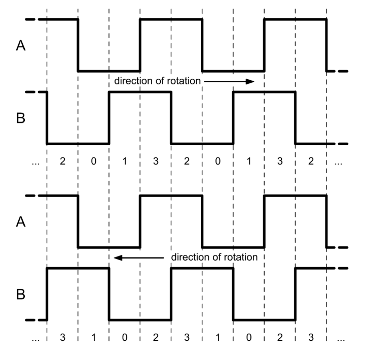
Spinning a properly wired rotary encoder produces a series of pulses on its A & B pins. To determine the spinning direction from these two signals all that is needed is to delay one of them by one step and then EXOR the two together.
Example
Suppose 'A' = '00110011...' and 'B' = '01100110...', then delay signal 'A', say, by one step to get '01100110...'. EXOR-ing the delayed 'A' with 'B' gives '00000000...'. When it is spinning in the other direction, then 'A' = '11001100...' ('B' unchanged), and 'A' delayed by one step is '10011001...'. EXOR-ing the delayed 'A' with 'B' now gives '11111111...'.
Spinning clockwise the rotary encoder generates the sequence is 0-1-3-2, anticlockwise it is 0-2-3-1.
Make it analog
Looking at the signals 'A' and 'B' together as a parallel bus allows us to consider them as a 2-bit binary value that can take on four values: 0b00, 0b01, 0b10 and 0b11 (Grey code). Multi-bit binary values can be converted to a single analog voltage using a digital-to-analog converter (DAC). That is what we will do here.
R-2R resistor network
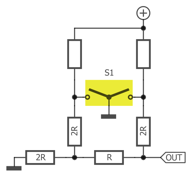
A common, simple DAC can be built with a so-called R-2R resistor network. Such a network consists of a bunch of resistors with only two values: R and 2R. For each bit two resistors are needed, every extra bit adds two resistors. A 2-pin rotary encoder therefore needs four resistors.
Four resistors make up a 2-bit R-2R DA converter.
Pull-up resistors are required too, otherwise there is no voltage to convert.
Such a circuit produces an analog voltage that takes on four values. The signal can be sampled with an AD converter and then decoded to recover the signals 'A' and 'B'. These can then be processed further in the same way as for a "normal" rotary encoder.
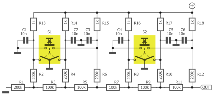
Practical design of the described method to connect two rotary encoders with built-in pushbuttons to a single MCU analog input pin.
Capacitors C1 to C6 provide contact debouncing.
A practical implementation
Two rotary encoders with integrated pushbuttons require a 6-bit DA converter. A microcontroller with a built-in 10-bit AD converter can easily decode the composite signal as it will have a 4-bit margin per bit, allowing the use of 5% resistors (1% would be better of course). Suitable microcontrollers are abundant, for instance the ATmega328 as found on an Arduino Uno board.
In a real-life implementation the value of R in the R-2R network must be much larger than the pull-up resistors to avoid the latter from influencing the R-2R ratio too much. At the same time, the pull-ups must not be too small, otherwise the current flowing through the switch contacts would be too high.
2R resistors are simply two R resistors in series.
Capacitors are needed to debounce the mechanical contacts to avoid that might otherwise cause interference between the two encoders.
Software
In the download section you can find an Arduino sketch that decodes the circuit above. An LTspice simulation is available too.
Want to build a project?
Bring your design to life with the Elektor PCB Service, powered by Eurocircuits. Upload the project files and order professionally manufactured PCBs or assembled boards through a proven European production platform.
Supporting KiCad, Eagle, Gerber, and ODB++ formats, the service is suitable for everything from prototypes and validation builds to series production and volume manufacturing.
Elektor Magazine has been one of the leading sources of information on electronics for engineers, designers, start-ups and companies for 65 years. Our magazine is powered by an active community of electronics engineers – from students to professionals – who are passionate about designing and sharing innovative ideas.
For them, we publish hundreds of items a year, in formats such as articles, videos, webinars, and other learning formats. Our mission is to share knowledge in every possible way and inspire readers with the latest developments within the electrical engineering sector.
Thank you for your vote!
Leave further comments in the fields below.
Thank you for your vote!
If you wish to leave a comment with your rating, please first use the login below. If not, just close this window.

Discussion (1 comment)