
Telegram interface for alarm control unit
Control interface allowing to manage the functions of an alarm control unit from the Telegram interface
Introduction:
During the containment related to COVID19, I had all the leisure to read the April/May issue of Elektor and especially the very interesting article by L.Lemmens concerning the implementation of a doorbell via Telegram allowing to warn the user on his mobile phone and possibly to open a door remotely.
I own a professional alarm system that is about ten years old, very reliable but not remotely controlled, and I don't want to change it for all that...
The idea came to me to create an interface card with 4 inputs allowing: to visualize the switching on and off of the central alarm station, the triggering of the siren, the disappearance of the sector, the triggering of the fire alarm and two relay outputs for the switching on and off of the fire alarm.
Description:
The interface uses an ESP32 module to manage the messages via Telegram. For the Telegram parameterization, we can read again Elektor article dedicated to this subject.
The blue led lights up when the interface connects to the WIFI network. It ensures that the connection is working properly.
The "OPTION" jumper when it is present allows you to check the status of the WIFI connection, by default every 12 hours a "Connection OK" message is sent to the Telegram application.
This test ensures that the internet connection and the interface are working.
The 4 inputs can be configured via jumpers either in "open collector" mode with a +5V pull-up resistor, or controlled by a +12V from the alarm control unit. The status of the inputs are displayed by yellow led.
Most of the alarm central units on the market have outputs controlled in positive security, the disappearance of the +12V triggers the siren. As for the led indicating the activation of the control unit, this is controlled by an open collector circuit (the led is switched on when it is off and off when the alarm is on).
Mains presence detection is provided by a relay or an open-collector output. If your alarm control unit does not provide this information, a simple 230V relay can be used as an indicator. It should be wired in maintained mode, this allows feedback in case of a power failure or a coil fault.
For fire detection, the information is available most of the time via a relay.
To start up the alarm control unit, it usually works in pulse mode, which allows several switch-on units to be wired in parallel.
In my case there is one input for the start and another one for the stop. Some models have only one input to manage the start and stop.
The manual of your control unit should be able to enlighten you on this subject.
The JP4 jumper allows you to validate the connection test via the box or the router, by default, it sends a message every 12 hours.
The interface can be updated remotely via the OTA and the WIFI network, this avoids having to dismantle the module for a possible update.
The entries are used this way in my configuration with a sending to the Telegram application :
- Input1: Indication of the alarm control unit on and off.
- Input2: Indication of alarm central unit start and stop.
- Input3: Indication of presence and absence of mains.
- Input4: Fire detection on/off indication.
Both outputs are impulse controlled by the Telegram interface and allow :
- Output1: Activation of the alarm control unit.
- Output2: Switching off the alarm control unit.
Electronics:
The power supply of the assembly is made from the 12V of the alarm central via the connector X5, one passes by the diode D2 which protects the electronics against a polarity inversion, and then by voltage regulator IC1 in order to obtain a 5V to supply the assembly and the ESP32.
The rest of the electronics is very simple, for the relays they are supplied with 12V and controlled by the MOS transistors Q1 and Q2, two visual led indicate the status of the relays.
The configuration of the inputs is managed by two jumpers, depending on the selected mode:
- Controlled by the +12V in the case of input IN1, jumper JP1 is connected between 1-2 and jumper 3 between 1-2. The voltage is applied through resistor R3, jumper JP1, LED LD-2, optocoupler OK1 and jumper JP3 which closes the assembly at 0V.
- Open collector" mode control in the case of input IN1, jumper JP1 is connected between 2-3 and jumper 3 between 2-3. The +5V is applied through resistor R1, jumper JP1, LED LD-2, optocoupler OK1 and jumper JP3 which connects the assembly to 0V through connector X1.
The output of the optocoupler is connected to the +3V3 through the 1K resistor R4, which together with the 100nF capacitor C1 forms an RC network used to filter any possible bounces.
Jumper JP2 allows possible tests for maintenance or software.
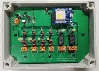
The printed circuit board is double-sided, the wiring does not pose any particular problem.
The PCB is designed for a Fibox 150/50 cabinet.
Software:
The software was written under Arduino and takes again a small part of the code described in Elektor " ESP32 doorbell for Telegram ", one will be able to read the article for the parameter setting and the explanation of the operation of Telegram.
The display language in Telegram can be selected via the preprocessor directive #define EN or #define FR. By default it is in English, just put the unused "define" as a comment.
This function allows you to have only one version of the software, which is very practical for possible evolutions, the software is commented in French and English.
The beginning of the program gathers all the variables: name of the WIFI network and the password, the key of the " BOTtoken ", the parameter setting of the relay impulse time in ms and the time delay between two control messages of the WIFI connection in hours.
Then we find the relay management functions, as well as the "bot.sendMessage" functions managing the messages sent either in French or in English through the instructions "#ifdef FR / #elif /defined(EN) and #endif".
The output management routine is managed in this part, we test the following instruction => if ( text == "/March"), if it's ok we activate the output relay and send to Telegram a "bot.sendMessage" indicating the correct taking into account of the order.
The "Void setup" function is used to set up the serial port via the USB of the ESP32 module for debugging.
The OTA function is then initialized to allow the downloading of updates. Please note that this function is only operational after the program has been loaded via USB for the first time.
The WIFI connection test routine is then launched, if it is correct, the blue LED LD1 "WIFI ON" is lit. Then we define the management of the inputs, in this case detection on a rising and falling edge.
The call of the routine "handleNewMessages" allows to process the commands of the incoming messages.
As mentioned in Elektor's article, the program needs to have the ID of the chat recorded in the "ThisChat" variable after receiving the "/start" command from the Telegram application.
The main program controls the change of state of the inputs in a loop, as soon as a change occurs, a message is sent via the "bot.sendMessage" function to telegram.
The program then tests the jumper JP4, if this one is in the low state we send periodically a message "Connection OK", this one is defined in the variable "tempo_msg_ok".
As soon as the jumper is set, we receive a message "WIFI test activated".
Then the program tests the elapsed time for sending messages, the last part permanently tests the WIFI connection and in case of loss of this one turns off the blue led LD1 "WIFI ON".
The program is commented and cut into easily identifiable routines, the comments are in French and English.
Conclusion:
The assembly has been working for two months without any problem, I made it in two copies.
I noticed during my tests a small bug related to the main loop timing, namely, when two events happen at the same time, only one is seen.
In "normal" operation, this should not affect the correct operation.
Last precision, the installation is powered by the alarm central, remember to put on UPS inverter your box or router in case of power failure...
During the containment related to COVID19, I had all the leisure to read the April/May issue of Elektor and especially the very interesting article by L.Lemmens concerning the implementation of a doorbell via Telegram allowing to warn the user on his mobile phone and possibly to open a door remotely.
I own a professional alarm system that is about ten years old, very reliable but not remotely controlled, and I don't want to change it for all that...
The idea came to me to create an interface card with 4 inputs allowing: to visualize the switching on and off of the central alarm station, the triggering of the siren, the disappearance of the sector, the triggering of the fire alarm and two relay outputs for the switching on and off of the fire alarm.
Description:
The interface uses an ESP32 module to manage the messages via Telegram. For the Telegram parameterization, we can read again Elektor article dedicated to this subject.
The blue led lights up when the interface connects to the WIFI network. It ensures that the connection is working properly.
The "OPTION" jumper when it is present allows you to check the status of the WIFI connection, by default every 12 hours a "Connection OK" message is sent to the Telegram application.
This test ensures that the internet connection and the interface are working.
The 4 inputs can be configured via jumpers either in "open collector" mode with a +5V pull-up resistor, or controlled by a +12V from the alarm control unit. The status of the inputs are displayed by yellow led.
Most of the alarm central units on the market have outputs controlled in positive security, the disappearance of the +12V triggers the siren. As for the led indicating the activation of the control unit, this is controlled by an open collector circuit (the led is switched on when it is off and off when the alarm is on).
Mains presence detection is provided by a relay or an open-collector output. If your alarm control unit does not provide this information, a simple 230V relay can be used as an indicator. It should be wired in maintained mode, this allows feedback in case of a power failure or a coil fault.
For fire detection, the information is available most of the time via a relay.
To start up the alarm control unit, it usually works in pulse mode, which allows several switch-on units to be wired in parallel.
In my case there is one input for the start and another one for the stop. Some models have only one input to manage the start and stop.
The manual of your control unit should be able to enlighten you on this subject.
The JP4 jumper allows you to validate the connection test via the box or the router, by default, it sends a message every 12 hours.
The interface can be updated remotely via the OTA and the WIFI network, this avoids having to dismantle the module for a possible update.
The entries are used this way in my configuration with a sending to the Telegram application :
- Input1: Indication of the alarm control unit on and off.
- Input2: Indication of alarm central unit start and stop.
- Input3: Indication of presence and absence of mains.
- Input4: Fire detection on/off indication.
Both outputs are impulse controlled by the Telegram interface and allow :
- Output1: Activation of the alarm control unit.
- Output2: Switching off the alarm control unit.
Electronics:
The power supply of the assembly is made from the 12V of the alarm central via the connector X5, one passes by the diode D2 which protects the electronics against a polarity inversion, and then by voltage regulator IC1 in order to obtain a 5V to supply the assembly and the ESP32.
The rest of the electronics is very simple, for the relays they are supplied with 12V and controlled by the MOS transistors Q1 and Q2, two visual led indicate the status of the relays.
The configuration of the inputs is managed by two jumpers, depending on the selected mode:
- Controlled by the +12V in the case of input IN1, jumper JP1 is connected between 1-2 and jumper 3 between 1-2. The voltage is applied through resistor R3, jumper JP1, LED LD-2, optocoupler OK1 and jumper JP3 which closes the assembly at 0V.
- Open collector" mode control in the case of input IN1, jumper JP1 is connected between 2-3 and jumper 3 between 2-3. The +5V is applied through resistor R1, jumper JP1, LED LD-2, optocoupler OK1 and jumper JP3 which connects the assembly to 0V through connector X1.
The output of the optocoupler is connected to the +3V3 through the 1K resistor R4, which together with the 100nF capacitor C1 forms an RC network used to filter any possible bounces.
Jumper JP2 allows possible tests for maintenance or software.
The printed circuit board is double-sided, the wiring does not pose any particular problem.
The PCB is designed for a Fibox 150/50 cabinet.
Software:
The software was written under Arduino and takes again a small part of the code described in Elektor " ESP32 doorbell for Telegram ", one will be able to read the article for the parameter setting and the explanation of the operation of Telegram.
The display language in Telegram can be selected via the preprocessor directive #define EN or #define FR. By default it is in English, just put the unused "define" as a comment.
This function allows you to have only one version of the software, which is very practical for possible evolutions, the software is commented in French and English.
The beginning of the program gathers all the variables: name of the WIFI network and the password, the key of the " BOTtoken ", the parameter setting of the relay impulse time in ms and the time delay between two control messages of the WIFI connection in hours.
Then we find the relay management functions, as well as the "bot.sendMessage" functions managing the messages sent either in French or in English through the instructions "#ifdef FR / #elif /defined(EN) and #endif".
The output management routine is managed in this part, we test the following instruction => if ( text == "/March"), if it's ok we activate the output relay and send to Telegram a "bot.sendMessage" indicating the correct taking into account of the order.
The "Void setup" function is used to set up the serial port via the USB of the ESP32 module for debugging.
The OTA function is then initialized to allow the downloading of updates. Please note that this function is only operational after the program has been loaded via USB for the first time.
The WIFI connection test routine is then launched, if it is correct, the blue LED LD1 "WIFI ON" is lit. Then we define the management of the inputs, in this case detection on a rising and falling edge.
The call of the routine "handleNewMessages" allows to process the commands of the incoming messages.
As mentioned in Elektor's article, the program needs to have the ID of the chat recorded in the "ThisChat" variable after receiving the "/start" command from the Telegram application.
The main program controls the change of state of the inputs in a loop, as soon as a change occurs, a message is sent via the "bot.sendMessage" function to telegram.
The program then tests the jumper JP4, if this one is in the low state we send periodically a message "Connection OK", this one is defined in the variable "tempo_msg_ok".
As soon as the jumper is set, we receive a message "WIFI test activated".
Then the program tests the elapsed time for sending messages, the last part permanently tests the WIFI connection and in case of loss of this one turns off the blue led LD1 "WIFI ON".
The program is commented and cut into easily identifiable routines, the comments are in French and English.
Conclusion:
The assembly has been working for two months without any problem, I made it in two copies.
I noticed during my tests a small bug related to the main loop timing, namely, when two events happen at the same time, only one is seen.
In "normal" operation, this should not affect the correct operation.
Last precision, the installation is powered by the alarm central, remember to put on UPS inverter your box or router in case of power failure...
Want to build a project?
Bring your design to life with the Elektor PCB Service, powered by Eurocircuits. Upload the project files and order professionally manufactured PCBs or assembled boards through a proven European production platform.
Supporting KiCad, Eagle, Gerber, and ODB++ formats, the service is suitable for everything from prototypes and validation builds to series production and volume manufacturing.
Made in Europe. Fast. Reliable. Professional.
Discussion (2 comments)