
USB-DMX Scene Controller
This device contains a USB-DMX converter (isolated) and a small memory chip. Make your scenes on your computer with Freestyler, and upload the file into this device.
This device contains a USB-DMX converter (isolated) and a small memory chip. Make your scenes on your computer with Freestyler, and upload the file into this device. Since it is standalone, push Start and let the USB-DMX controller control the lightshow.
Concept: (OLD)
We could use a MCU with integrated USB hardware like an ATmega32U4 or use an external FT232 so we don't need to concern ourselves with USB.
We could use a rotary encoder with integrated pushbutton to preform the scene 'start/stop' functionality, turning it one way to go to the next scene, the other way to go back a scene.
To store the scenes non-volitile memory(MRAM, FRAM, etc..) connected via SPI could be used.
To isolate the RS485 bus an ADM2487E could be used combined with a DA2303_AL transformer. The chip supports high enough frequencies for DMX to work.
Update:
Perhaps a display to show the current scene number could be added.
Update 26-9-2012:
DMX512 explained:
DMX512 is a protocol which runs on RS485 hardware. In general the master only sends and never recieves.
The bit time is 4uSec so that is a frequency of 250K.
The bit time is 4uSec so that is a frequency of 250K.
A packet(or "scene") consists of a 'BREAK', a 'mark after break(MAB)' and then 513 channels follow.
- 'BREAK' Has to be longer than 92uSec.
- 'Mark after break (MAB)' Has to be longer than 12 uSec.
- A channel slot consists of a start bit, eight data bits and two stop bits.
- Channel slot 0 is usually eight zeroes.
- Channel 1 till 512 contain the data.
There has to be at least 1204uSec between the leading edges of the 'BREAK' in two packets(scenes). That means that if you use fewer than 24 channels you have to either pad a few channels with zero bytes, or you have to stretch the 'BREAK' or 'MAB' specs.
That means that the maximum scene update speed is 830 packets per second.
And when you use all the channels it's only 44 packes per second.
The slowest allowed speed is 1 packet per second.
The slowest allowed speed is 1 packet per second.
So if you want more time between scenes, the old scene will have to be retransmitted, this won't cause a change in the connected devices because the data is the same.
Concept: (NEW)
I switched it all around and opted for an FPGA based solution.
I added a display for a more complex user interface.
But the idea that you can set a bunch of scenes to non volatile memory and play it back remains the same. But I thought of some extra features.
Some extra(planned) features:
- 'Scene save' You can pass a signal from a lighting console through our board and capture the scene, save it to the FRAM while actually seeing it appear in your light installation.
- 'Channel stack' Same as above but doesn't create a new scene, but stacks the channels. For instance you have a 16channel scene, because your lighting console only has a maximum of 16channels, and you want to let other lights do something as well. Simply change your settings and stack that new scene on top of the old one, thus resulting in a single 32channel scene.
- 'Scene loop' Select the scenes you wish to loop through and the speed at which you want to do so.
Plan:
Design a schematic, and the PCB.
In the mean time get to know the FPGA with a development board.
- Try some simple IO, a button switching a LED
- Implement some sort of UART so the RS485 driver can be used. (timing can be checked this way)
- Design a SPI controller
- Design a controller to connect a HD44780 based LCD.
- Figure out how to use the internal fpga SRAM
(When the hardware is finished.)
- Test the designed FPGA program in actual hardware.
- Design an FRAM memory controller that functiones via the SPI controller.
- Expand the feature set so all of the desired features are eventually included
Update 19-12-2012:
I chose a FPGA instead of a microcontroller and did develop this board, so I thought it would be a good idea to use that Elektor FPGA board as a basis to build this project on.
Also, I've been looking around Opencores.org for some usable code/IP I could find. Maybe they are directly usable, if not, it's open source, I could edit it. Probably faster than developing from scratch.
LCD controllers
http://opencores.org/project,16x2_lcd_controller
http://opencores.org/project,hd44780_driver
SPI controller
http://opencores.org/project,spi_master_slave
Update 07-feb-2013:
I've started on a schematic design, some footprints and started looking at suitable enclosures. Metal would be nice and sturdy, but there is more choice when concidering plastic ones as well.
Update 27-feb-2013:
I've made a small test setup to test the LCD control code and it works!
I've implemented a small ROM in the onchip BRAM. The .coe file was easy to make in radix 16. On screen text can be translated from ASCII to HEX with a free online calculator.
Update 07-mar-2013:
The PCB is almost done, it fits the Hammond 1455K1202 enclosure. The userinterface is mounted on the reverse side of the PCB, so the PCB will be inverted in the enclosure. This way everything stays on one PCB. I chose not to include switchable rs485 termination, a user accesable switch would require a larger enclosure or would compromise isolation. Users can always solder a 120 ohm resistor to a spare XLR-3 connector to terminate the line.
Update 14-mar-2013:
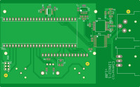
I ordered the PCB and the required components. I added PDFs of the schematic and the PCB layers. I also added a colourised version generated by eurocircuits and a component list.
Update 20-mar-2013:
Due to the incomplete dimension specs of the enclosure I had to make a v1.10 version of the PCB. It should fit better this time.
I added JP1 in the schematic so people can choose whether or not to connect the K2 cable shield to the isolated ground.
(120612)
Want to build a project?
Bring your design to life with the Elektor PCB Service, powered by Eurocircuits. Upload the project files and order professionally manufactured PCBs or assembled boards through a proven European production platform.
Supporting KiCad, Eagle, Gerber, and ODB++ formats, the service is suitable for everything from prototypes and validation builds to series production and volume manufacturing.
Made in Europe. Fast. Reliable. Professional.
Discussion (1 comment)