
USB-GAD-Platform
Lowcost wideband signal generator, oscilloscope, logic analyzer and more.. On the "USB GAD_base" board are multiple channels of highspeed DAC's that can GENERATE-wideband analog signals, there are multiple channels of highspeed ADC's they can ACQUIRE wideband analog signals, and last but not least there are "DIGITAL IO's", that can handle FAST digital signals. So GAD stands for Generate, Acquire and Digital :-)
A project(s) proposal, that can be build up by means of sub-projects.
The maker-community uses a lot of MCU-board, with or without wireless connections of some sort. The MCU's can have sensor-inputs, which can be digital-signals or analog-signals, or it can drive actuators, which also can be digital-signals or analog-signals. But these signals will always be narrow banded. The MCU's are not very well capable of producing more wideband signals. It can produce or acquire a multitude of audio band-with signals. But a multitude of video channels?? Generating or acquire video bandwith signals might be possible, but will ask a lot from the MCU's, and if possible, only one channel might be possible. But at least there are very wel affordable MCU-board's available to be in the price range of a Electronic-Maker enthousiast or hobbyist.
A programmable device that is better capable of handling a multitude of channels is an FPGA (Field Programmable Gate Arrays). There exist FPGA evaluation boards, but they are mostly very expensive, and there are not many FPGA board with wideband (multi channel)DAC's and (multi channel)ADC's on board.
But a Electronic-Maker enthousiast or hobbyist would be pleased to have some generator and meassurement equipment, like a (arbitrary)function/signal generator, or an oscilloscope or may be even a spectrum analyzer.. and the list can go on.., a network analyzer (e.g. LRC meter with 20..50Mhz bandwidth), and of course a digital logic analyzer/generator, but more applications are possible:
Multichannel Software Defined Radio reciever and or transmitter (might be used to steer the radio-signal-beams).. Or a radar or sonar application, Video/Camera (mixing console) , AI-stuff, and plenty more.
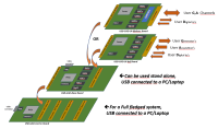
Ok.. time to reveal, what "USB-GAD-Flatform" is about...I will show the total full-fledged system first..
Full_fledged_GAD_system.png: From bottom to top...a 'USB-GAD-Carrier Board', this starts with a (highspeed) USB3 via a USB-c connector that can be connected to a PC or Laptop. On that board is a chip from FTDI for the USB, but not a FTDI-chip as you would find on a MCU-board.. but a Highspeed USB3 capable device, the FT601, this has a 32-bit wide bus of 100Mhz (so 400MBytes/Sec = 3.2Gbps) connected to a FPGA, in this case a low-cost Intel(Altera) Cyclone 10 (more on that later). The FPGA drives/receive digital signals towards the connectors shown.
On such a connector you can plug a "USB-GAD-base board": see USB_GAD_base.png.
On the board are multiple channels of DAC's that can GENERATE-wideband analog signals, there are multiple channels of ADC's they can ACQUIRE wideband analog signals, and last but not least there are "DIGITAL IO's", that can handle FAST digital signals. So GAD stands for Generate Acquire and Digital
Note that also this "USB-GAD-base board" has a USB-c connector, and an FPGA.. this enables to use this board stand alone. So you do not need the full system.
And, the "USB-GAD-base board" also has a connector, on which you can connect a "USB-GAD-UI-buf board" or a "USB-GAD-UI-diplexer board"
Why a "USB-GAD-UI-buf board" (UI stands for User Interface) ?
Well the "USB-GAD-base board" produce the basic handling of wideband signals, it does not scale, it does not amplify to produce power...
By having several versions of "USB-GAD-UI-buf boards", you can put electronics wel suited for the application in mind, on those boards.
Let me note: That having a "USB-GAD-Base Board" , this will be the generic/general basis for plenty applications that need programable wide-band analog sigals, and fast digtal signals.
Then Include software API's to control the "USB-GAD-Base Board". Then this is a good generic/general platform, that can be extended/build on to realize more and more applications.
In this manner, not each application needs to be started from scratch.
Please note the included pictures: USB_GAD_base.png, USB_GAD_UI.png, and USB_GAD_carrier.png.
Plenty of sub-projects/articles can follow during the building up of this project.
Each sub project can be build and described in the magazines.
Start with:
1a) "USB-GAD-Base Board", FTDI USB3, FPGA-firmware
1b) the software with some API's and a GUI (in Qt in C++ on a PC/labtop), displaying multichannel signals, signal processing e.g. FFT's.
2a) a first of a range of "USB-GAD-UI-buf board", first the most common desired application, with using and extending the software.
2b) a next "USB-GAD-UI-buf board" ...
3) adding a USB_GAD_carrier board, so you can plug in the already several developed application, and have it connected to one PC.
This project will be very educational, as well.
-------
The reason for Cyclone 10, it is more easy to handle than Xilinx and there is an interesting FREE software tooling option for the Cyclone 10 devices. There are two options..
Using a Cyclone 10LP, this you can handle with Quartus prime Lite for FREE. But using that 'LP-version' of the Cyclone10 FPGA will have a limmitation on the LVDS signal speed (like 640 Mpbs).
A better option is using Cyclone 10GX this you can handle with Quartus prime Pro. What??.. Yes Quartus prime Lite for FREE, but Quartus prime Pro is expensive, very expensive,, out of the range of Electronic-Maker enthousiast or hobbyist expensive.
BUT.. when you use the Cyclone 10GX, yes ONLY the Cyclone 10GX.., THAN you can use the Quartus prime Pro, it will generate the output files at no costs.
Being capable to use the Cyclone 10GX, will enable the "USB-GAD" with higher bandwith ADC and DAC, because the higher LVDS signal speed (like 1250 Mpbs).
..This is a first published description of the USB-GAD idea, and it is property of the above author.
'Copyright' ©, 29-08-2022, Theo Mulder.
Want to build a project?
Bring your design to life with the Elektor PCB Service, powered by Eurocircuits. Upload the project files and order professionally manufactured PCBs or assembled boards through a proven European production platform.
Supporting KiCad, Eagle, Gerber, and ODB++ formats, the service is suitable for everything from prototypes and validation builds to series production and volume manufacturing.
Made in Europe. Fast. Reliable. Professional.
Discussion (0 comments)