
Voice Activated Turn Controller
This is a voice activated turn controller project. The project receives voice commands and activated LEDs (or relays) positioned at LEFT, RIGHT, UP and DOWN. The project can be used to control for example the movements of a mobile robot, or a robot arm.
Note: This project is built, tested and is FULLY WORKING.
Project video link: https://www.youtube.com/watch?v=E81K4yy0-ss
Voice activated turn controller: This project is based on the concepts of artificial intelligence where a voice activated turn controller is designed using the MAX78000FTHR microcontroller development board. The project consists of 4 LEDs positioned as Left, RIGHT, UP, and DOWN. The LEDs can be turned ON by giving the voice commands LEFT, RIGHT, UP, or DOWN. One possible use of the project is to control the movements of a mobile robot by voice commands.
At the heart of the MAX78000FTHR is a MAX78000 Cortex-M4 ARM based microcontroller with FPU. Additionally, the board contains 512KB flash memory, 128KB SRAM, 16KB cache, Convolutional Neural Network Accelerator, VGA image sensor, digital microphone, RGB LED, pushbuttons, microSD card adapter, microUSB connector, stereo audio CODEC, SWD debugger, virtual UART port, and many I/O ports.
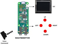
Block Diagram: Figure 1 shows the block diagram of the project. A 2.4 inch ILI9341 controller based TFT FeatherWing 240x320 pixel touch-screen TFT display is used at the front end of the project to display the user commands and responses. 4 LEDs are connected to the project to simulate 4 relays or 4 lights. The LEDs are configured to represent the directions LEFT, RIGHT, UP, and DOWN and are connected to the processor I/O ports through 1K current limiting resistors. The LEDs are controlled by giving voice command such as LEFT, RIGHT, UP, DOWN or STOP (to turn all LEDs). The project can be used for example to control the movements of a model vehicle, moving robot arm, etc.
Circuit Diagram: Figure 2 shows the circuit diagram of the project. 4 LEDs are connected to the I/O ports through 1K current limiting resistors. As mentioned earlier, the LEDs are used for testing the project, but they can very easily be replaced with 3.3V operating relays and used to control e.g. AC devices if required.
The TFT display is connected to the MAX78000FTHR via the SPI bus interface. Pins MISO, MOSI, SCK and CS of the SPI bus are connected to pins P0_6 (MISO), P0_5 (MOSI), P0_7 (SCK), and P0_11 (CS) of the development board. Pin D/C of the TFT display is connected to pin P0_8, and Vcc and GND are connected to +3.3V and GND pins of the MAX78000FTHR.
The circuit was built on a breadboard and connections were made using jumper wires. Figure 3 shows the project built on a breadboard.
Power is supplied to the circuit through its mikroUSB cable which should be connected to the USB port of a computer during the program development.
Operation of the project: The operation of the project is shown in Figure 4 as a state diagram. The following sounds are recognized by the project (invalid spoken commands are rejected by the project):
SHEILA: Attention sound. When this sound is spoken, a prompt will be displayed on the TFT telling
the user that he/she can speak a valid command. You should wait until the prompt is
displayed at the bottom of the screen before saying another command.
LEFT: Turn ON the LEFT LED
RIGHT: Turn ON the RIGHT LED
UP: Turn ON the UP LED
DOWN: Turn ON the DOWN LED
STOP: Turn OFF all LEDs
Note that only one LED can be turned ON by any command. When a command is given to turn ON a LED, the LED which is currently ON (if any) is automatically turned OFF. This behaviour can be changed in software if required.
Some example commands are given below in sequence:
SHEILA LEFT Turn ON left LED
SHEILA RIGHT Turn OFF all lights and then turn ON RIGHT LED
SHEILA UP Turn OFF all lights and then turn ON UP LED
SHEILA STOP Turn OFF all lights
The TFT display will show both the user commands and the state of the activated relays as a verification. A small delay (few seconds) is inserted after each command so that the user can see the commands and responses on the TFT display.
Program listing: The 20 keywords in the supplied Maxim project kws20_demo has been changed to include the word SHEILA. The CNN training program was ran on a Linux Ubuntu operating system after creating a WMware virtual machine on a Windows 10 machine with an i7 CPU, 100GB disk space, and 12GB free memory, without a special GeoForce GPU. After training the new words, the created cnn.c, cnn.h files and the weights.c and weights.h files were copied to the workspace and program main.c under folder kws20_demo was modified for this project. The full main.c program listing is given in Figure 5 as a PDF file.
Function Detected_Word detects the spoken word and returns an integer number which is used to identify the detected sound. Number 100 is returned if a non-valid sound is detected by the program. The temperature control cycle is entered every time the program goes round its loop.
Function ALLOFF turns OFF all LEDs (or deactivated all relays if relays are used). The voice commands are given the following integer numbers to identify them:
10=SHEILA, 11=LEFT, 12=RIGHT, 13=UP, 14=DOWN, 15=STOP
The ELEKTOR lego was converted into a bitmap image and then into a c file, and is displayed when the project is started (see the section on running the project).
Figures 6.1 to 6.11 show snapshots of the TFT display from the beginning to giving commands to control the LEDs.
Example run of the project: An example run of the project is shown in the You Tube video link. Notice that the ELEKTOR logo is displayed when power is applied to the project, or when the Reset button is pressed. Then, a short screen is displayed as a header which gives very brief information about the project. The user is then prompted to speak the required valid commands to control the LEDs (or relays).
Suggestions for future work:
The project can be upgraded such that the command acceptance and the state of the LEDs (or relays) can be spoken on a speaker. This will make the project more fun and also more professional. Additional commands can be used to turn OFF the individual LEDs whenever required by giving voice commands. These can be done with very are simple modifications to the existing program.
Project video link: https://www.youtube.com/watch?v=E81K4yy0-ss
References
https://datasheets.maximintegrated.com/en/ds/MAX78000.pdf
https://www.maximintegrated.com/en/design/technical-documents/app-notes/7/7417.html
https://www.maximintegrated.com/en/design/videos.html/vd_1_rtp4xipe#popupmodal
https://datasheets.maximintegrated.com/en/ds/MAX78000FTHR.pdf
https://www.maximintegrated.com/content/dam/files/design/tools/ev-kits/schematics/max78000-fthr-schematic.pdf
https://www.maximintegrated.com/en/design/software-description.html/swpart=SFW0010820A
https://github.com/MaximIntegratedAI/MaximAI_Documentation/blob/master/MAX78000_Feather/README.md
https://www.maximintegrated.com/en/design/technical-documents/app-notes/7/7359.html
https://www.maximintegrated.com/en/products/microcontrollers/MAX78000.html
Project video link: https://www.youtube.com/watch?v=E81K4yy0-ss
Voice activated turn controller: This project is based on the concepts of artificial intelligence where a voice activated turn controller is designed using the MAX78000FTHR microcontroller development board. The project consists of 4 LEDs positioned as Left, RIGHT, UP, and DOWN. The LEDs can be turned ON by giving the voice commands LEFT, RIGHT, UP, or DOWN. One possible use of the project is to control the movements of a mobile robot by voice commands.
At the heart of the MAX78000FTHR is a MAX78000 Cortex-M4 ARM based microcontroller with FPU. Additionally, the board contains 512KB flash memory, 128KB SRAM, 16KB cache, Convolutional Neural Network Accelerator, VGA image sensor, digital microphone, RGB LED, pushbuttons, microSD card adapter, microUSB connector, stereo audio CODEC, SWD debugger, virtual UART port, and many I/O ports.
Block Diagram: Figure 1 shows the block diagram of the project. A 2.4 inch ILI9341 controller based TFT FeatherWing 240x320 pixel touch-screen TFT display is used at the front end of the project to display the user commands and responses. 4 LEDs are connected to the project to simulate 4 relays or 4 lights. The LEDs are configured to represent the directions LEFT, RIGHT, UP, and DOWN and are connected to the processor I/O ports through 1K current limiting resistors. The LEDs are controlled by giving voice command such as LEFT, RIGHT, UP, DOWN or STOP (to turn all LEDs). The project can be used for example to control the movements of a model vehicle, moving robot arm, etc.
Circuit Diagram: Figure 2 shows the circuit diagram of the project. 4 LEDs are connected to the I/O ports through 1K current limiting resistors. As mentioned earlier, the LEDs are used for testing the project, but they can very easily be replaced with 3.3V operating relays and used to control e.g. AC devices if required.
The TFT display is connected to the MAX78000FTHR via the SPI bus interface. Pins MISO, MOSI, SCK and CS of the SPI bus are connected to pins P0_6 (MISO), P0_5 (MOSI), P0_7 (SCK), and P0_11 (CS) of the development board. Pin D/C of the TFT display is connected to pin P0_8, and Vcc and GND are connected to +3.3V and GND pins of the MAX78000FTHR.
The circuit was built on a breadboard and connections were made using jumper wires. Figure 3 shows the project built on a breadboard.
Power is supplied to the circuit through its mikroUSB cable which should be connected to the USB port of a computer during the program development.
Operation of the project: The operation of the project is shown in Figure 4 as a state diagram. The following sounds are recognized by the project (invalid spoken commands are rejected by the project):
SHEILA: Attention sound. When this sound is spoken, a prompt will be displayed on the TFT telling
the user that he/she can speak a valid command. You should wait until the prompt is
displayed at the bottom of the screen before saying another command.
LEFT: Turn ON the LEFT LED
RIGHT: Turn ON the RIGHT LED
UP: Turn ON the UP LED
DOWN: Turn ON the DOWN LED
STOP: Turn OFF all LEDs
Note that only one LED can be turned ON by any command. When a command is given to turn ON a LED, the LED which is currently ON (if any) is automatically turned OFF. This behaviour can be changed in software if required.
Some example commands are given below in sequence:
SHEILA LEFT Turn ON left LED
SHEILA RIGHT Turn OFF all lights and then turn ON RIGHT LED
SHEILA UP Turn OFF all lights and then turn ON UP LED
SHEILA STOP Turn OFF all lights
The TFT display will show both the user commands and the state of the activated relays as a verification. A small delay (few seconds) is inserted after each command so that the user can see the commands and responses on the TFT display.
Program listing: The 20 keywords in the supplied Maxim project kws20_demo has been changed to include the word SHEILA. The CNN training program was ran on a Linux Ubuntu operating system after creating a WMware virtual machine on a Windows 10 machine with an i7 CPU, 100GB disk space, and 12GB free memory, without a special GeoForce GPU. After training the new words, the created cnn.c, cnn.h files and the weights.c and weights.h files were copied to the workspace and program main.c under folder kws20_demo was modified for this project. The full main.c program listing is given in Figure 5 as a PDF file.
Function Detected_Word detects the spoken word and returns an integer number which is used to identify the detected sound. Number 100 is returned if a non-valid sound is detected by the program. The temperature control cycle is entered every time the program goes round its loop.
Function ALLOFF turns OFF all LEDs (or deactivated all relays if relays are used). The voice commands are given the following integer numbers to identify them:
10=SHEILA, 11=LEFT, 12=RIGHT, 13=UP, 14=DOWN, 15=STOP
The ELEKTOR lego was converted into a bitmap image and then into a c file, and is displayed when the project is started (see the section on running the project).
Figures 6.1 to 6.11 show snapshots of the TFT display from the beginning to giving commands to control the LEDs.
Example run of the project: An example run of the project is shown in the You Tube video link. Notice that the ELEKTOR logo is displayed when power is applied to the project, or when the Reset button is pressed. Then, a short screen is displayed as a header which gives very brief information about the project. The user is then prompted to speak the required valid commands to control the LEDs (or relays).
Suggestions for future work:
The project can be upgraded such that the command acceptance and the state of the LEDs (or relays) can be spoken on a speaker. This will make the project more fun and also more professional. Additional commands can be used to turn OFF the individual LEDs whenever required by giving voice commands. These can be done with very are simple modifications to the existing program.
Project video link: https://www.youtube.com/watch?v=E81K4yy0-ss
References
https://datasheets.maximintegrated.com/en/ds/MAX78000.pdf
https://www.maximintegrated.com/en/design/technical-documents/app-notes/7/7417.html
https://www.maximintegrated.com/en/design/videos.html/vd_1_rtp4xipe#popupmodal
https://datasheets.maximintegrated.com/en/ds/MAX78000FTHR.pdf
https://www.maximintegrated.com/content/dam/files/design/tools/ev-kits/schematics/max78000-fthr-schematic.pdf
https://www.maximintegrated.com/en/design/software-description.html/swpart=SFW0010820A
https://github.com/MaximIntegratedAI/MaximAI_Documentation/blob/master/MAX78000_Feather/README.md
https://www.maximintegrated.com/en/design/technical-documents/app-notes/7/7359.html
https://www.maximintegrated.com/en/products/microcontrollers/MAX78000.html
Want to build a project?
Bring your design to life with the Elektor PCB Service, powered by Eurocircuits. Upload the project files and order professionally manufactured PCBs or assembled boards through a proven European production platform.
Supporting KiCad, Eagle, Gerber, and ODB++ formats, the service is suitable for everything from prototypes and validation builds to series production and volume manufacturing.
Made in Europe. Fast. Reliable. Professional.
Discussion (1 comment)