
Yet Another GPS Alarm Clock
Another GPS Alarm Clock? You've got to be kidding! Read on to see how a new, easy to use touchscreen library manages the clock.
YAGAC
(Yet Another GPS Alarm Clock)
I have long been fascinated by time, as it is our most precious commodity. When my old store-bought, atomic clock controlled projection alarm clock failed, I decided to build my own… In short order, I purchased a new one because it became quickly obvious that building an alarm clock would be a bit of a task. However, the breadboard version is finished and works, and is worth sharing.
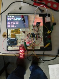
First and foremost, the user’s interaction with the clock is managed by a touch screen. This is a big deal because I have written (what I think, anyway) is a very easy to use library for managing screen graphics and using the touchscreen to drive user interactions. I have written an accompanying several page document that describes the structure and function of the library in detail. I urge readers to look at the clock’s code. I am hard-pressed to see how it could be simpler.
Second, I like this project because it uses logic level, low internal resistance MOSFETs. I think they are hugely underused by hobbyists and makers and have greatly simplified my life. Unless I need electrical isolation, these devices are my switch of choice.
Third, it uses the Teensy 3.5. If ever there were a lazy man’s development board, this is it. Huge number of pins, fast (32 bit), cheap, massive program space and RAM, built-in SD card reader, AND 5 volt tolerant. The last point is deceptively important, as it reduces part count and complexity when working with mixed 3.3V and 5V peripherals. I would recommend powering this project from a 5V supply that can source at least 500mA, and higher would be better (I like my power supplies to run cool and unstressed!)
I have not yet mounted the components. I plan to 3D print a housing, and I have a chunk of steel plate from a blown power supply that can act as weight and backbone within the housing. I plan to project the time onto my ceiling; the objective lens assembly from a broken set of binoculars is an effective lens. This is the reason for the two 4 digit displays.
Parts are sourced from pjrc.com (Teensy), allelectronics.com, and various vendors on eBay. I purchased the touchscreen display and controller from Adafruit. They are quite expensive compared to other vendors, but fairness dictates that I provide some remuneration to the source of the underlying graphics library.
Basic program structure starts with the usual #define statements, variable declarations, and object instantiations. Setup() initializes various objects, and retrieves various program parameters from EEPROM.
Loop() retrieves the current time from the DS3231 module, displays the time on the four digit displays, and updates the touchscreen display as well. loop() also checks to see if alarm conditions have been met. The program then calls manageTouch() which handles user interactions with the screen. Rather than returning the location of a screen touch event, it returns the unique ID number of the screen graphic that was touched. A switch() block then hands off execution to a series of specialized functions.
I have deliberately written the code so as to be readable and use a minimum of hotshot programming techniques (e.g., no conditional ternary operator stuff). The only place where code gets a bit hairy is in the guts of the library, where accessing member variables of an object stored in a vector array is necessary. These calls require both dereferencing and typecasting objects stored in the vector array. This is intrinsically and irreducibly complex.
What is the need for logic level MOSFETs? One is to turn the alarm beeper on and off. I really didn’t want to drive the beeper directly from the Teensy. Additionally, controlling what is for all intents and purposes a generic switch permits design flexibility for the alarm device. The other use is for the GPS unit. Relatively inexpensive GPS modules are VERY power hungry. Because the GPS module is setting (or resetting) an extremely accurate clock chip, it will be used infrequently. No reason to leave it on all the time. This would be particularly important for adapting the design to battery power/backup.
To make this project work:
Connect peripherals to Teensy as described in the schematic
Write the RA8875.txt file to a microSD card that is readable by the Teensy and insert the card in the SD reader
Load GPS_Clock6.0 into the Teensy
Let the GPS antenna have a clear view of the sky
Touch GPS sync
My apologies to my European friends and colleagues. I have only set this up for North American time zones and daylight savings time. However, this can be easily changed
(Yet Another GPS Alarm Clock)
I have long been fascinated by time, as it is our most precious commodity. When my old store-bought, atomic clock controlled projection alarm clock failed, I decided to build my own… In short order, I purchased a new one because it became quickly obvious that building an alarm clock would be a bit of a task. However, the breadboard version is finished and works, and is worth sharing.
First and foremost, the user’s interaction with the clock is managed by a touch screen. This is a big deal because I have written (what I think, anyway) is a very easy to use library for managing screen graphics and using the touchscreen to drive user interactions. I have written an accompanying several page document that describes the structure and function of the library in detail. I urge readers to look at the clock’s code. I am hard-pressed to see how it could be simpler.
Second, I like this project because it uses logic level, low internal resistance MOSFETs. I think they are hugely underused by hobbyists and makers and have greatly simplified my life. Unless I need electrical isolation, these devices are my switch of choice.
Third, it uses the Teensy 3.5. If ever there were a lazy man’s development board, this is it. Huge number of pins, fast (32 bit), cheap, massive program space and RAM, built-in SD card reader, AND 5 volt tolerant. The last point is deceptively important, as it reduces part count and complexity when working with mixed 3.3V and 5V peripherals. I would recommend powering this project from a 5V supply that can source at least 500mA, and higher would be better (I like my power supplies to run cool and unstressed!)
I have not yet mounted the components. I plan to 3D print a housing, and I have a chunk of steel plate from a blown power supply that can act as weight and backbone within the housing. I plan to project the time onto my ceiling; the objective lens assembly from a broken set of binoculars is an effective lens. This is the reason for the two 4 digit displays.
Parts are sourced from pjrc.com (Teensy), allelectronics.com, and various vendors on eBay. I purchased the touchscreen display and controller from Adafruit. They are quite expensive compared to other vendors, but fairness dictates that I provide some remuneration to the source of the underlying graphics library.
Basic program structure starts with the usual #define statements, variable declarations, and object instantiations. Setup() initializes various objects, and retrieves various program parameters from EEPROM.
Loop() retrieves the current time from the DS3231 module, displays the time on the four digit displays, and updates the touchscreen display as well. loop() also checks to see if alarm conditions have been met. The program then calls manageTouch() which handles user interactions with the screen. Rather than returning the location of a screen touch event, it returns the unique ID number of the screen graphic that was touched. A switch() block then hands off execution to a series of specialized functions.
I have deliberately written the code so as to be readable and use a minimum of hotshot programming techniques (e.g., no conditional ternary operator stuff). The only place where code gets a bit hairy is in the guts of the library, where accessing member variables of an object stored in a vector array is necessary. These calls require both dereferencing and typecasting objects stored in the vector array. This is intrinsically and irreducibly complex.
What is the need for logic level MOSFETs? One is to turn the alarm beeper on and off. I really didn’t want to drive the beeper directly from the Teensy. Additionally, controlling what is for all intents and purposes a generic switch permits design flexibility for the alarm device. The other use is for the GPS unit. Relatively inexpensive GPS modules are VERY power hungry. Because the GPS module is setting (or resetting) an extremely accurate clock chip, it will be used infrequently. No reason to leave it on all the time. This would be particularly important for adapting the design to battery power/backup.
To make this project work:
Connect peripherals to Teensy as described in the schematic
Write the RA8875.txt file to a microSD card that is readable by the Teensy and insert the card in the SD reader
Load GPS_Clock6.0 into the Teensy
Let the GPS antenna have a clear view of the sky
Touch GPS sync
My apologies to my European friends and colleagues. I have only set this up for North American time zones and daylight savings time. However, this can be easily changed
Want to build a project?
Bring your design to life with the Elektor PCB Service, powered by Eurocircuits. Upload the project files and order professionally manufactured PCBs or assembled boards through a proven European production platform.
Supporting KiCad, Eagle, Gerber, and ODB++ formats, the service is suitable for everything from prototypes and validation builds to series production and volume manufacturing.
Made in Europe. Fast. Reliable. Professional.
Updates from the author