
ChipCap2 humidity sensor BOB [140154]
We designed this little board as part of a larger project published on our Labs-website, see http://www.elektor-labs.com/project/feuchtegesteuerte-kellerl-ftung-humidity-basement-ventilation-140154.13770.html. The humidity sensors used in the original design are rather expensive, and we need two of them for this ventilation system.
We designed this little board as part of a larger project published on our Labs-website, see http://www.elektor-labs.com/project/feuchtegesteuerte-kellerl-ftung-humidity-basement-ventilation-140154.13770.html. The humidity sensors used in the original design are rather expensive, and we need two of them for this ventilation system. We decided to use the more affordable Chipcap2 humidity sensors from Amphenol for this.
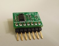
The breakout board presented here allows the user to work and experiment with the CC2A humidity/temperature sensors from Amphenol Advanced Sensors. Although these tiny components can be soldered by hand, their footprint doesn’t match with any experimenting board, so a small PCB with a standard 2.54mm pitch pin header connecting all sensor pins to the outside world will make (breadboard) prototyping a lot easier.
The CC2A can be used either in I2C mode (like in our application) or in Pulse Density mode (PDM), in which case two separate pins -after some passive filtering- provide analog temperature and humidity signals. Our breakout board layout is suited for both modes –some components must be changed-, but here we will focus on I2C only. Read the ‘ChipCap 2 application guide’ for more information on the PDM mode.
The board has 10k pull-up resistors on the SDA and SCL lines, which will do for standard speed I2C. Connecting more boards to the bus can be done without modifications, although four (resulting in a 2k5 pull-up, about the minimal value for I2C) should be considered as a maximum for the number of boards. If more sensors are needed, desolder their pull-up resistors R1 and R2.
I2C devices have a fixed address on the I2C bus, many of them have one or more external address pins to make it possible to hook up more identical devices on unique addresses to the same bus. The ChipCap2 however has a predefined address stored in its internal EEPROM. This means that by factory default all devices respond to the same address, which can only be altered by software. There are other ways: the sensors only need 75uA, so it would also be possible to switch the power supply of every individual device on just before a measurement is taken, but –apart from the extra wiring- this is not the most elegant solution.
On https://github.com/circuitsforfun/ChipCap2 we found a very useful, extensive Arduino (and Python) library written by Richard Wardlow, which contains most definitions and functions needed to communicate with the CC2A sensors in I2C mode. There’s also a simple sketch that writes some settings to the sensor and reads values, which are displayed via the serial monitor of the Arduino programming environment. This example can be used for initial testing of the breakout board.
The library also contains functions to handle the READY (End Of Conversion) pin of the CC2A, but we prefer to poll the sensor’s status bits via I2C to determine if humidity and temperature values are ready to be read. It’s more how I2C was meant to be, it saves an I/O line of the microcontroller and of course it saves one wire for every sensor in the system.
Unfortunately the library does not support re-programming the I2C address, so we wrote a simple sketch (CC2A_set_I2C_address.ino) to perform this task. Note that this will only work during a short interval after the sensor is powered on, this is why its VCC power supply pin must be connected to an Arduino digital output (PB0) pin, which is controlled by software. In this sketch two constants are defined:
CURRENT_I2C_ADDRESS = 0x28 (factory default!)
NEW_I2C_ADDRESS = 0x22 (or any other unique value between 0x00 and 0x7f)
The address is changed by simply writing to EEPROM address 0x1C, the Custom Configuration Register of the CC2A. Note that we are writing to a 16-bit register and that the I2C address is found in the lower seven bits of this word. All higher bits are all zeroes by factory default, most of them are assigned to special user configurable settings of the alarm pins of the sensor. These setting will be reset to factory default by this sketch!
It certainly is a good idea to put a small sticker with the new I2C address on the backside of the breakout board!!!
After changing the address, the sketch reads data from this new I2C address every five seconds. Both temperature and relative humidity are displayed via the serial monitor of the Arduino IDE.
Want to build a project?
Bring your design to life with the Elektor PCB Service, powered by Eurocircuits. Upload the project files and order professionally manufactured PCBs or assembled boards through a proven European production platform.
Supporting KiCad, Eagle, Gerber, and ODB++ formats, the service is suitable for everything from prototypes and validation builds to series production and volume manufacturing.
Made in Europe. Fast. Reliable. Professional.
Discussion (2 comments)