
Optical Fingerprint Recognition with the GT-521F52
Be Careful With the GT-521F52’s Connectors
According to the datasheet the module can be powered from 3.3 to 6 volts. Connecting the power supply requires care and attention, because the highly symmetrical module has two identical 4-pin connectors on either side of the sensor that both accept a supply voltage, but not the same, and they are wired differently. To distinguish between the two connectors use the group of tiny SMT parts placed in one corner of the board as orientation mark (see the yellow circle in the photo below).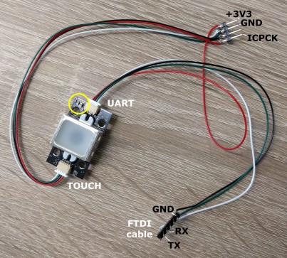
The GT-521F52’s Serial Interface
The connector closest to the yellow circle has the serial port on it and accepts a 3.3 to 6 volts supply voltage. The serial port signals (default setting is 9600n81) are specified as 3.3 V signals and a level converter would be needed to connect it to for instance a 5-volt system like an Arduino Uno. Direct hooking up to a computer is possible with a 3.3-volt “FTDI” cable. Remember that FTDI cables always have 5 V on their supply wire, even the 3.3-volt ones.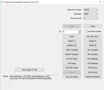
Integrated Touch Sensor
The “other” connector is for the touch interface and expects 3.3 volts maximum. The metal sensor frame functions as a touch sensor. The signal ICPCK available on this connector indicates if a finger is on the sensor or not. Touching the sensor can also be used to wake up the module from idle mode. Updating the firmware (no new firmware available at the time of writing) requires this connector too.Read full article
Hide full article
Discussion (0 comments)