
Hands-Free Measurements with Sensepeek Tools
on
When testing a prototype, when repairing or calibrating electronic circuits, connecting test cables or probes is often a challenge. In many cases, especially with surface mounted devices (SMDs), test clips will not fit on the components’ terminals, and a pin-shaped test probe needs one of your hands to keep it connected to the test point. Your other hand may be needed to hold the PCB in place, or to operate measuring instruments. And of course, if you want to measure at more points simultaneously, you’ll be short of hands. Tools from Sensepeek will help in all respects, freeing your hands and helping you to concentrate on more important things than ensuring that the probe stays where it should be to get the measurements done.
Sensepeek Kit
With good-old through-hole (TH) technique, components have connection pins to which usually a clamp or hook can be easily attached, which in turn ensures a good connection of a test cable or oscilloscope probe to the point where we want to measure. But in SMD technology, this kind of accessories are not useful: there are no physical pins to which you can clamp anything, or the connections are so close together that even the smallest measuring clip you can find will cause short circuits with neighbouring pins. Of course, pointed test probes have been in use for years, but the disadvantage of such probes is that you have to hold them in the right place yourself and you have to be careful not to slip them and cause a short circuit.
Through the years, a lot of mechanical measuring aids have been invented or improvised to construct hands-free probes, making sure that a test pin stays in place and has enough contact pressure for reliable measurements. I have tried many of these more or less useful methods, but the set from Sensepeek that will be discussed here is the most solid and well thought-out solution that I have had on my workbench so far. Let’s take a look at what’s in this kit.
Fixing the PCB
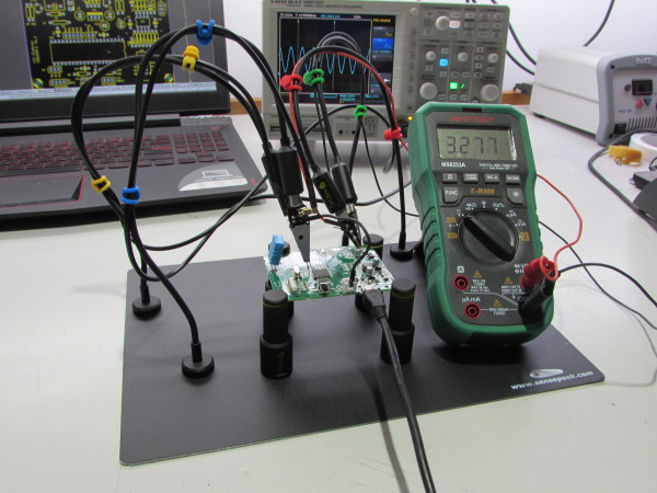
A good measurement set-up starts with a measurement object that remains firmly in place, which is a prerequisite for hands-free measurement, especially with small PCBs. Traditionally, some sort of vice or a so-called “third hand” is used for this task, but the Sensepeek PCBite contains four metal clamps with magnetic bases that are used to fix the board onto a metal base plate (see Figure 1).
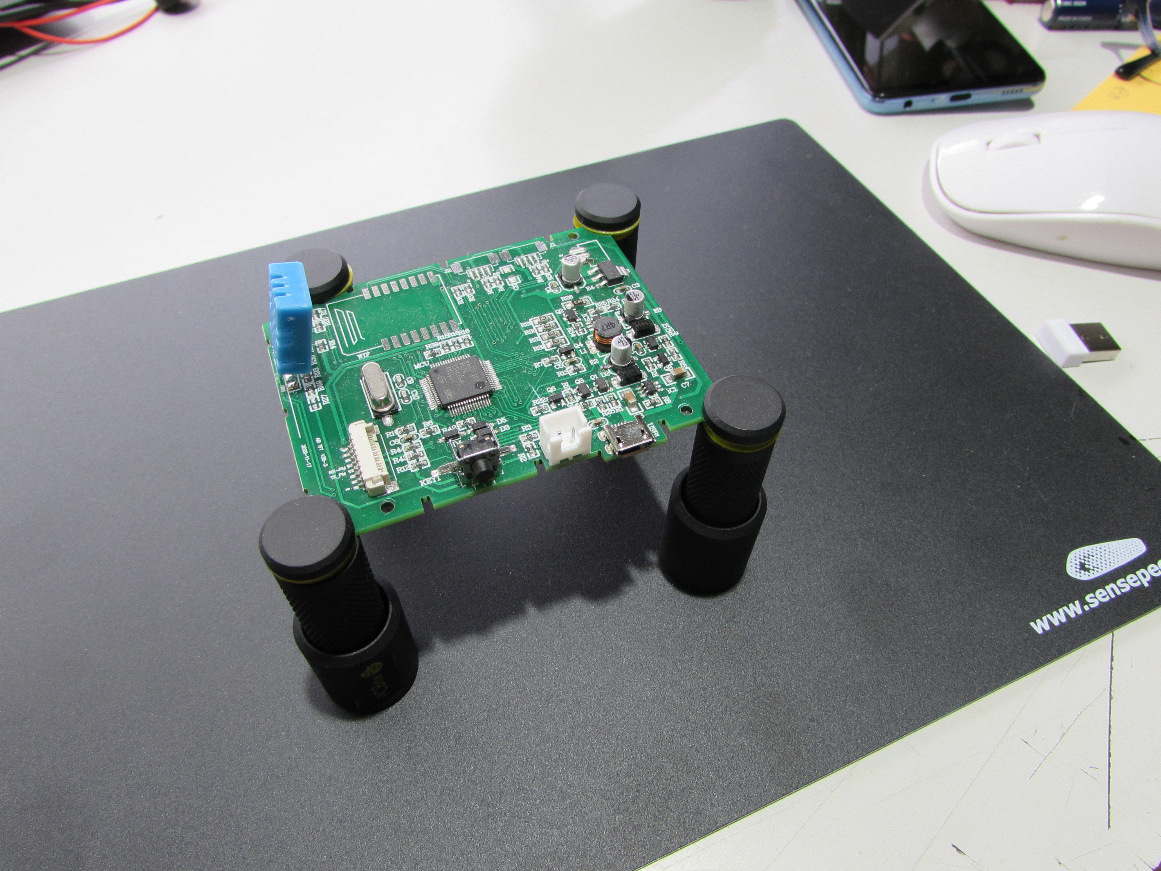
This is a very stable solution that will work for most PCBs, regardless of their shape. The jaws of the clamps hold the edges of the board and are insulated with plastic rings. The base plate itself can be insulated with a self-adhesive plastic foil that is included in the set.
Hands-Free Probes
Four “ordinary” SP10 1:1 probes and two SP200 1:10 200 MHz oscilloscope probes are supplied in the Sensepeek kit. Each measuring probe comes with a gooseneck probe arm on a magnetic foot that holds on the metal base plate, just like the clamps for fixing the PCB. This ensures that the probe head comes and stays in exactly the right position on the PCB. The probe head is screwed to the thread at the end of the arm, the measuring cable is connected to the head and guided along the gooseneck probe arm. There are color coded cable holders in eight different colors to easily identify the correct channel on your measurement tool, and to keep the cables away from your PCB under test, as shown in Figure 2.
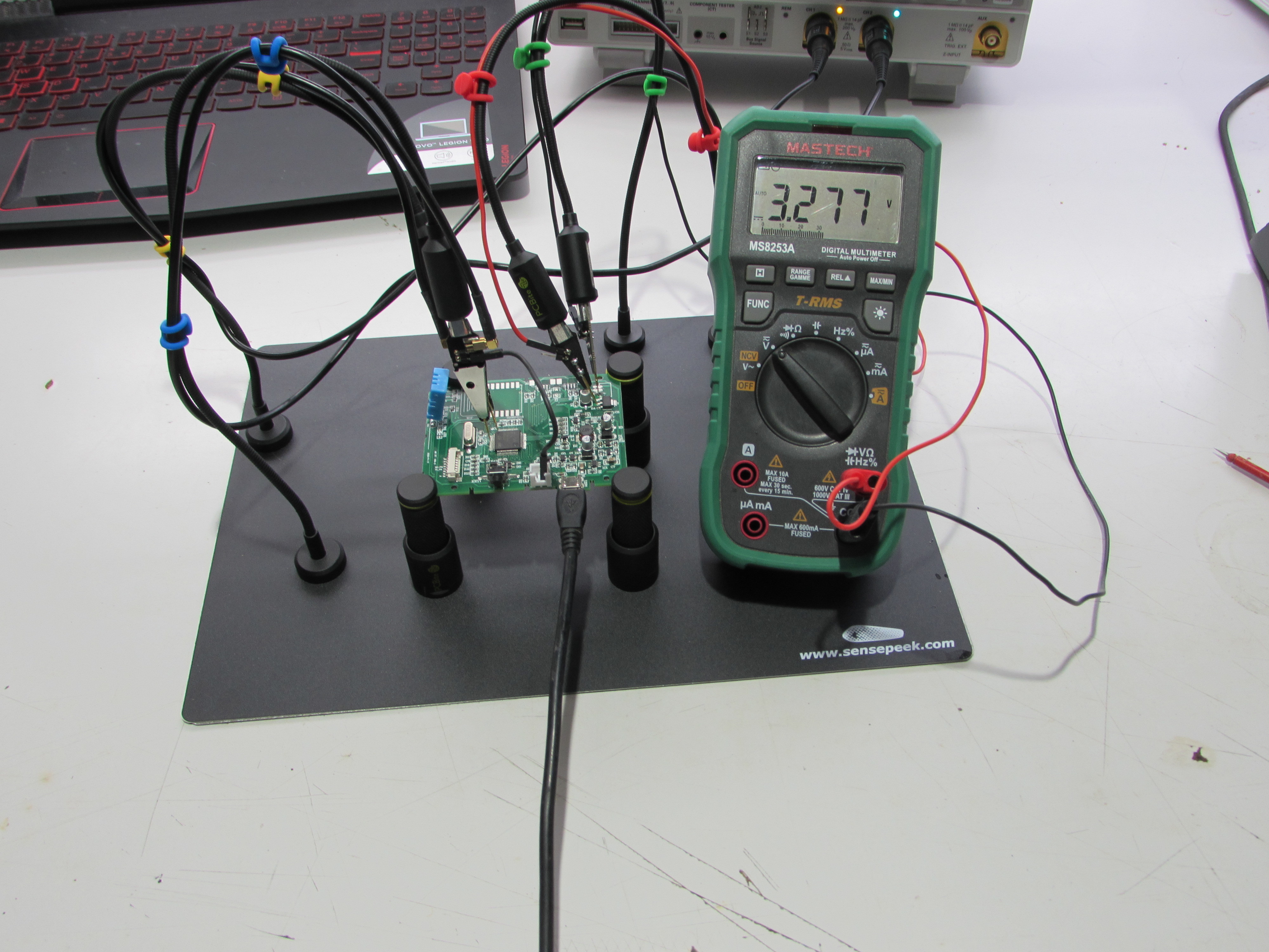
The goosenecks are best compared to the flexible arms used for aligning microphones and desk lamps, but the ones for Sensepeek hands-free probes are much more flexible. This flexibility kind of surprised me, but it turns out that the arms do a perfect job! The probes all have a spring-loaded, needle-shaped measuring tip and the procedure of fixing them at the measuring point is surprisingly simple to do: take the probe head, move the tip to the correct position, gently press the needle in and slowly release the probe. You may need to move the magnetic base of the arm to the right position for the tip to stay on the correct spot, but it’s relatively easy to do. It sounds too simple to be true, but it really works great, better than any other hands-free probe I have ever used (Figure 3). When correctly setup, the measuring tips will even stay put if you accidently nudge the workbench or base plate — within limits of course.
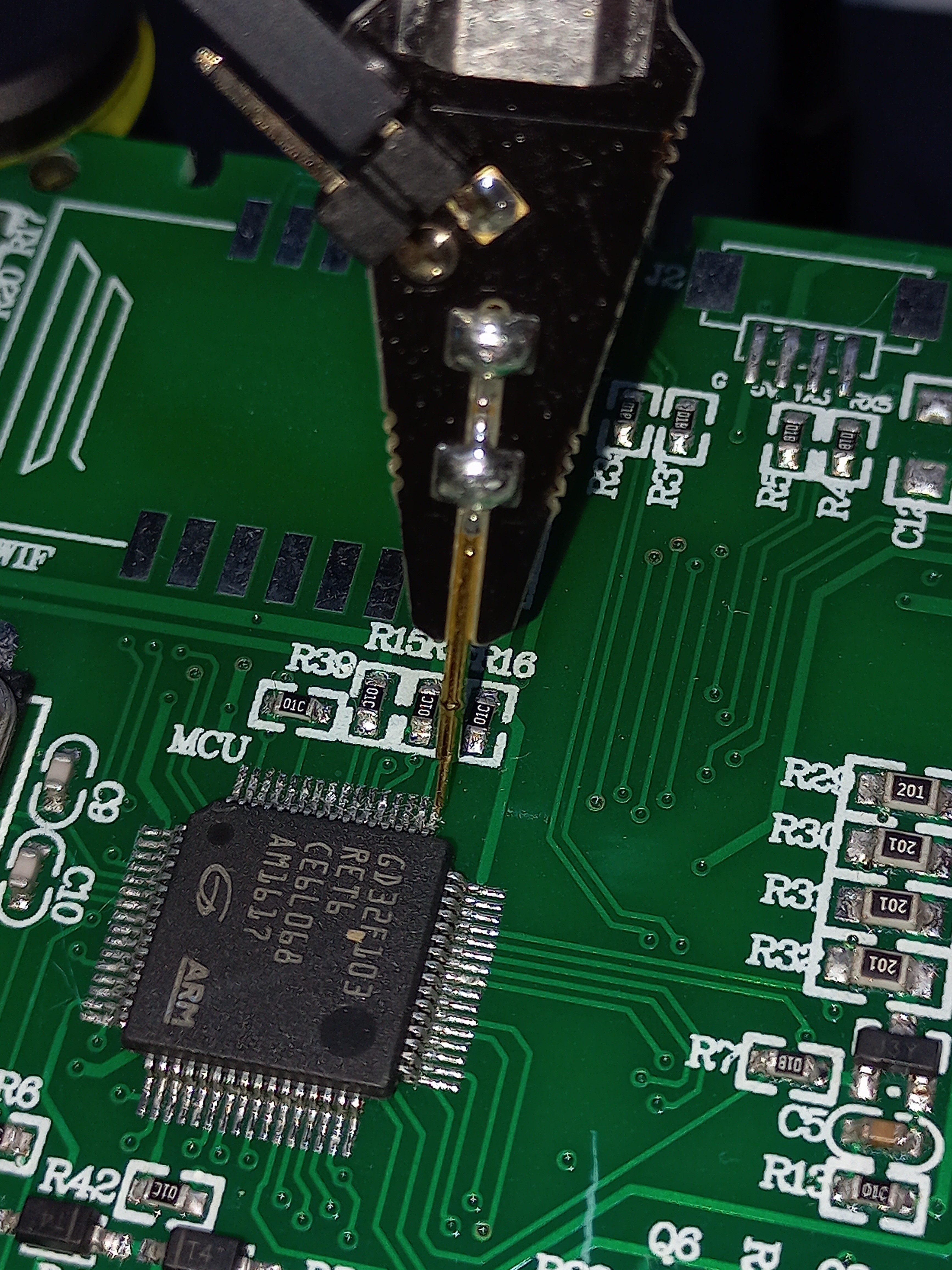
To work properly, the tips must be and stay sharp, they are available as spare part and easy to replace when blunt; there are already some spare ones supplied with the probe heads, be careful not to lose them when you open the zip-lock bags.
Two types of probes
According to the manual, an SP10 1:1 probe (Figure 4) is suitable for signal measurements and logic analyzers for high-speed serial communication interfaces like SPI, CAN, USB, JTAG, I2C, UART etc. The probes can also be used for resistance and voltage measurements, power and grounding of devices with continuous currents of maximum two ampere.
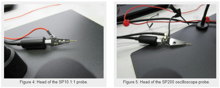
The 200 MHz bandwidth SP200 oscilloscope probe (Figure 5) has a fixed 1:10 attenuation ratio. It is a hands-free probe, using the same mechanical construction as an SP10 probe to fix the tip to the test point on the PCB. In all other respects, it is exactly the same as a “normal” 1:10 oscilloscope probe, with a frequency compensation trimmer that must be calibrated using the test signal on the oscilloscope, and a grounding wire that must — most ideally — be connected as close as possible to the test point. And exactly as with other probes, the way this grounding connection is made will sometimes be a compromise, unless there is a nearby GND pin on the PCB. The SP200 is supplied with a short grounding wire with a miniature clip and a longer wire that can be plugged onto a GND connector pin. Full electrical and mechanical data of the SP10 and SP200 probes are specified in the manuals [1] and [2].
The Sensepeek Solution
Even with the relatively basic 1:1 probes that are contained in this set, a data sheet is supplied with all its relevant technical specifications. I know: we are all technicians, and we will never (or hardly ever) read those documents, but the simple fact that these specifications do exist proves that this Sensepeek set is a well-designed and engineered toolkit. Admittedly: the kit is quite expensive, but you really get value for your money, the PCBite for holding the PCB works great, and I don’t want to miss these hands-free probes in my lab anymore!
Discussion (0 comments)