
I2C drivers for 7-segment-with-DP 5-mm RGB LED display
Drive your common anode or common cathode LED displays by I2C.
Related projects
By making a prototype to drive a display for demonstration to Elektor editorial staff, I imagined a future clock, operating in I2C.
Description
I had a pressing request, my son, having taken off, wanted to have an RGB Led clock like "at home, with a few different functions". Its specifications:4 RGB displays Different fade colors and speeds for each display.
1 LDR for brightness
2 touch keys,
1 -> low red night mode, Off/On,
2 -> temperature display (via DS18B20), date display GPS time setting. I added to it 1 Bluetooth HC06 module
1 nRF24+, as I have some radio sensors.
1 Arduino_Nano to drive it all.
Today, the prototype is being tested by its owner. Sorry, i digress, back to the I2C drivers.
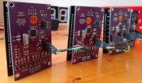
Each driver is equipped with an Atmega 328P-AU, external 16Mhz quartz clock for the PWM, it's better. The PCB is designed for wiring according to the type of LED used. By setting the 0 ohm resistor, the control choice is set. Note, it is possible to insert a low value resistor (33R), instead of a bridge, to best adjust the maximum brightnes, in order to avoid visual discomfort.
The line-segment transistors are of the NPN Led anode com or PNP Led cathode com type. The PWM line transistors are of the PNP Led anode com or NPN Led cathode com type. I used BSR14 (NPN) and BSR16 (PNP) For those who wish to use the object in SPI mode, I have provided the option (Pin SS). I deliberately avoided fixing the addresses of the displays by coding on the PCB, as I had been advised.This option restricts the possible number of displays to be controlled by the master (linked to the number of remaining pins on the Atmega of the back of the display)
I write a "byte_Code_I2C" to communicate with the display using the values from 0 to 255. Order from master, from 0 -> 255::
Numbers from 0 to 9
Letters from 10 to 30 (A,b,c,C...)
Others from 31 to 46 (= ° -....)
Auto color fades from 60 to 62 (possible...70)
Fixed colors 71 to 90
Bluetooth Color!!
Info from master processing bluetooth color order (for I2C clock to come:) 91: pwm_bluetooth -> bluetooth info (we listen to the following 3 values (eg (255;180;70)
Map fade speed from 100 to 200 for 15ms to 1s Brightness adjustment from 201 to 239 for pwm 0 to 100%
Management of dp from 247 to 254 (125 ms, 250 ms, 500 ms, 1s tempo dp blink, dp ever OFF, dp On, dp BLINK Off, dp BLINK On)
There are still free values. Each display has its address and a base code and executes the I2C actions according to the requests of the master. The object is programmable via ISP.
Video: https://youtu.be/CA6bTKupoS8
Want to build a project?
Bring your design to life with the Elektor PCB Service, powered by Eurocircuits. Upload the project files and order professionally manufactured PCBs or assembled boards through a proven European production platform.
Supporting KiCad, Eagle, Gerber, and ODB++ formats, the service is suitable for everything from prototypes and validation builds to series production and volume manufacturing.
Made in Europe. Fast. Reliable. Professional.
Updates from the author