
JOY-iT LCR-T7 Multi-Function Tester
on
Multi-function testers are always nice-to-haves for discrete components, for both passive and active parts. Sometimes values or type numbers are difficult to read and, in case of discrete semiconductors with exotic type numbers, you may want to check what kind of component it is. And even if you can visually identify the part, you may want to know if it still works and if it — to some degree — complies to its original specifications. This is where a tester like the JOY-iT LCR-T7 comes in handy: just a quick check which component we are dealing with, or at least to see if it is the part we expected it to be.
In other words, with this kind of equipment, it is easy to test discrete components, identify what kind of part it is and — in case of semiconductors — even to find out what the correct pinning is. As the name suggests, it is a tester, so don’t expect to get highly accurate measurements from this device. You shouldn’t demand that from a measuring device that costs less than three tenners.
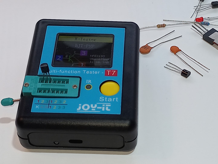
One of the nice things about the LCR-T7 is that it is very easy to operate: just connect the device under test (DUT) to the ZIF-socket strips on the front panel , either with or without the wires and clips provided with the tester and push the Start button. That’s it. The device will automatically recognize what type of component is connected and will display its main parameters and pinning (if and when applicable) on the LCD.
Supported Devices
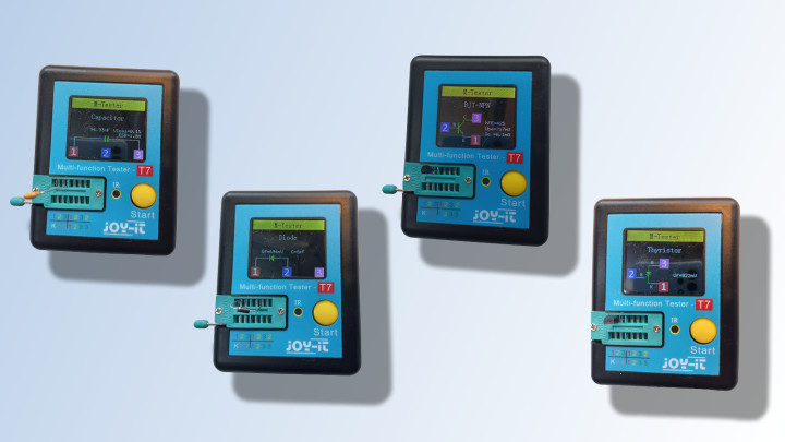
The list of components that can be tested with the JOY-iT LCR-T7 (see text box) is quite impressive for such a small and affordable device. The values that are measured and displayed depend on the type of component under test, of course. Figure 1 shows some results for different types of components, the manual [1] provides a complete overview for all components that can be tested.
Although Darlington transistors are not listed, it looks like the LCR-T7 still gives some useful information on these components. They can be identified by a high Vbe (> 0.7 V), and the identification of the pinning is correct for the Darlingtons I have tested. Don’t trust the other measurements that are displayed for this type of transistor, though.
Getting Started
After unpacking, the first thing to do is to charge the internal lithium battery using the micro-USB cable that is supplied with the LCR-T7. The bi-color LED next to the USB-connector will light red during charging, and green when the battery is fully charged. The tester can also be used if it is USB-powered. Perform the automatic calibration of the LCR-T7 by shorting the terminals (see Figure 2) and pressing the Start button.
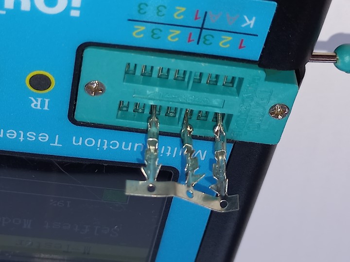
When about 22% of the calibration is done, the display will prompt you to remove the short circuits; when these are disconnected, the calibration will automatically proceed and finish. The manual doesn’t mention when or how often the tester needs to be recalibrated, but it won’t harm to do this every once in a while, I guess, especially when you if you’re not sure about the test results of a component.
For first tests, an electrolytical capacitor and an LED are supplied with this component tester. In my opinion, it would have been a better choice to add some three-legged discrete semiconductors to demonstrate the automatic device type and pin identification.
Connecting Components
The ZIF-socket for connecting DUTs (Figure 3) is an excellent solution; a simple, normal socket as found on many similar testers, wears in no-time.
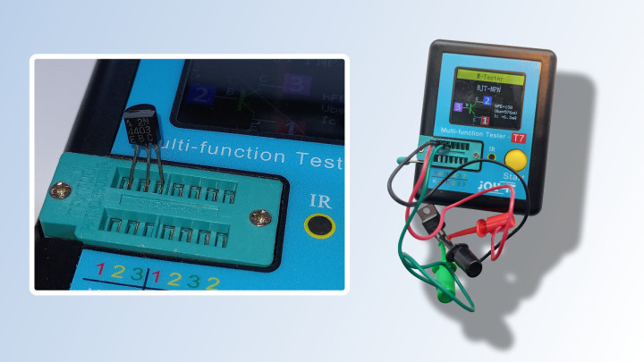
Three test clip cables are supplied for connecting components with thicker pins to prevent damage to the contacts of the ZIF socket. The complete upper row and the four rightmost connections of the lower row are used for most component testing, with “1”, “2” and “3” marking the location for the pins of the DUT. The three remaining pins to the left of the bottom row (marked “K” and 2 x “A”) are for testing Zener diodes with voltages up to 30 V.
IR-Detector
The LCR-T7 also has an integrated IR-detector that can decode and display the device and data codes of remote controls using the NEC protocol. For devices with other IR protocols, the tester shows a red dot in the corner of the screen when an IR signal is detected, so you can at least check if your remote control is working or not.
Simple Yet Useful
In all its simplicity, the LCR-T7 certainly is a useful piece of equipment. I do prefer a normal multimeter for measuring things like battery voltage and resistance, mostly because that is always on my workbench anyway. But for other components, especially for semiconductor parts, it is really great to quickly identify the type and pinning, and to get the main parameters on the display by simply connecting and pushing a button. And what we all like: the price is nice too!
Features and Specifications
MAIN FEATURES
| Measurable components | Resistor, capacitor, inductor, thyristor, TRIAC, (double) diode, Z-diode, field effect transistor, bipolar transistor, infrared RC |
| Supported IR-protocol | NEC (used by many manufacturers) |
| Display type | 1.8” TFT LCD (160 x 128 pixels) |
| Special features | Automatic calibration, One key operation |
| Built-in battery | Lithium-ion rechargeable, 3.7 V, 350 mAh |
MEASURING RANGES
| Capacitance | 25 pF - 100 mF |
| Resistance | 0.01 Ω - 50 MΩ |
| Inductance | 0.01 mH - 20 H |
| Battery | 0.1 V - 4.5 V |
| Z-diode voltage | 0.01 V - 30 V |
| Diode | UF < 4.5 V |
Discussion (2 comments)