
Review: The Joy-iT JDS2915 Signal Generator
on
Last spring my co-worker Harry Baggen reviewed the Joy-iT JDS6600 signal generator which is the big brother of the JDS2915. In his review he felt that the unit was let down by its cheap-looking plastic case. I’m sure he will be delighted that this smaller, cheaper, lower-frequency version from Joy-iT is housed in a more robust aluminium profile case. The model JDS6600 he reviewed has the same features as the JDS2915 on review here (except for its different frequency bandwidth and different case) so I will refer to his review and try to avoid repetition of common features by concentrating to other aspects of the unit.
Unboxing
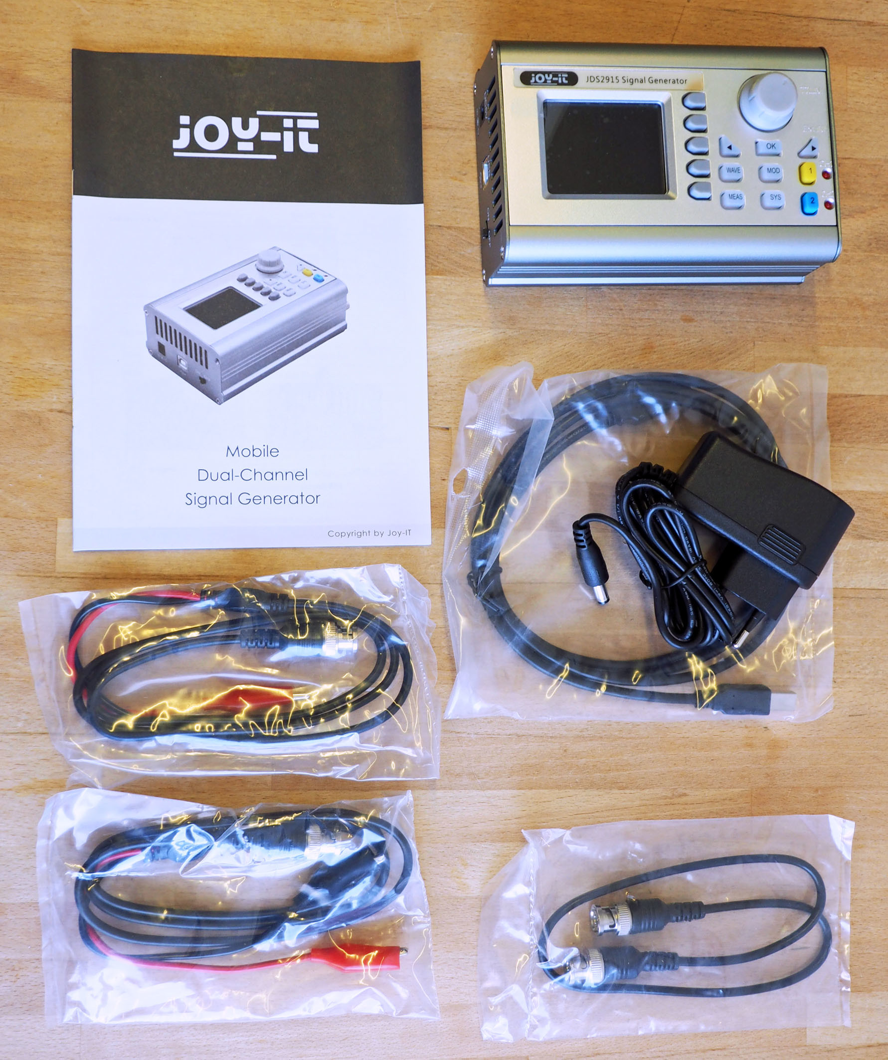
Figure 1 shows what comes in the box: In addition to the actual signal generator in a tough metal housing, there are two BNC cables with crocodile clips for the two signal outputs, a short cable with BNC plugs at both ends for connecting to other devices, and a USB 2.0 cable with a USB-A and USB plug for controlling the signal generator via a PC, a mains power adapter with a lead terminated in a barrel plug (5 V/2 A) and a thin DIN A5 sized manual.
A manual? Yes finally… a real manual! I spoke too soon; the tri-lingual (German, French and English) information booklet consists of just two pages for each language. A more comprehensive user manual can be found on the Joy-iT website (in German and English). You can also download a datasheet and the PC software for remotely controlling the signal generator (including some installation instructions).
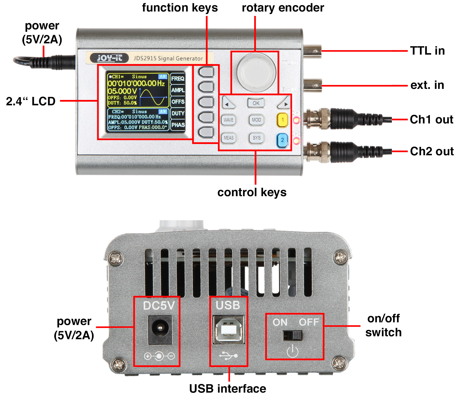
The thin DIN A5 booklet only indicates (Figure 2) which buttons do what. The thing I am not so keen on is the layout of the input and output connectors on the right side panel of the aluminium case and not on the front panel like the JDS6600. From an operators point of view there is practically no difference between the two models. The ‘Control buttons’ are mounted slightly lower on the JDS2915 and the shaft encoder is directly above them. On the JDS6600, this knob has been moved to the right.
Even before trying it out, I had concerns that the unit is quite lightweight and would need to be held down whenever I wanted to operate a pushbutton on the front panel. Indeed this turned out to be the case; there are no rubber feet on the underside of the case to prevent sliding.
Key Features of the JDS2915:
- Supply: Euro-style mains power supply rated 5 V / 2 A
- Two channel signal outputs with 50-Ω impedance
- Output signal ≤10 MHz: 0 to 20 VPP, in 1 mV steps
- Output signal >10 MHz: 0 to 10 VPP, in 1 mV steps
- Offset: -10 to + 10 V in 10 mV steps
- Output waveforms: sine, square, triangle, pulse, arbitrary etc.
- Frequency signals: 0 to 15 MHz, in 10 mHz steps
- Duty cycle (for pulse and triangular waveforms): 0.0 to 99.9%
- Special functions: sweep for sine and pulse waveforms
- Frequency counter: 0 to 100 MHz
- Frequency accuracy: ±22 ppm
- Frequency stability: ±1 ppm/3 h
- Amplitude stability: ±5%/5 h
- Digital signal resolution: 14 bit
- Signal sampling rate: 266 MS/s
- Dimensions: 145 x 95 x 55 mm (WxHxD)
- Weight: 450 g (without power supply)
- Current consumption at 5 V: max. 850 mA (measured)
- Display: 2.4” colour LCD
- Operation: keypad, encoder, Wi-Fi or remote via USB and PC app
In contrast to information given in the data sheet, the signal generator can also deliver pulses with a repetition rate up to 15 MHz. The output stage cannot supply a signal much greater than ± 10 V. If you increase the output DC offset to the maximum positive level of + 9.99 V, the output signal is limited to 200 mVPP. With a DC offset of -4 V for example, the available output swing is 12 VPP maximum.
To the bench...
If you have used a signal generator before, the operation of the JDS2915 (apart from the arbitrary signals) is fairly self-explanatory. I was able to produce any waveform and adjust the output without recourse to the PDF manual. The software manual for the JDS2915, is currently only available in German, and actually shows a picture of the JDS6600 signal generator in its plastic housing and makes reference only to the JDS6600 in the text. This makes me think that the JDS6600 series and the JDS2915 are, except for the casing, technically largely identical devices. The JDS2915 software documentation certainly looks like it was originally written for the JDS6600 model.
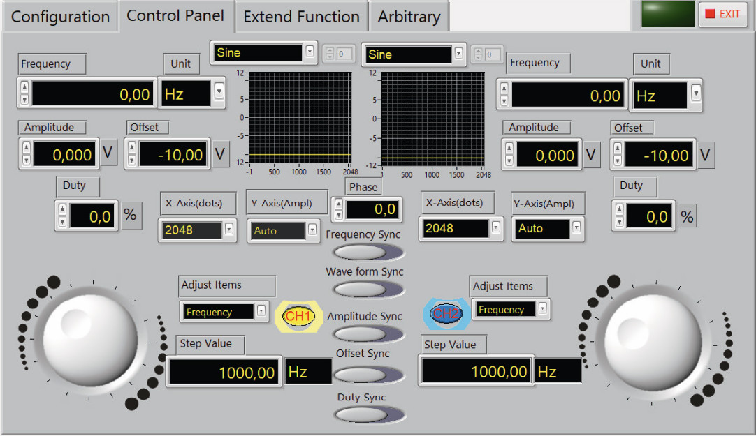
The software itself is a program created with LabView (Figure 3). This ‘4th generation programming language’ from National Instruments is more often used in a professional testing, measurement and control environment, to perform automated production testing. Although the drivers for linking signal generators together exist, they are not made available for downloading from Joy-iT (or the software producers). Consequently you are not able to integrate the signal generator into an automated test environment under LabView. That is a real shame — it would be a really cool feature.
Operation and signals
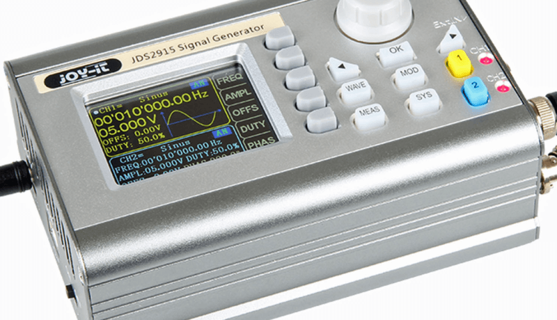
Figure 4 shows the display in three different modes (there are more). Above is the setting for a sinewave signal at 4 VPP and 1 kHz. The offset is +1.0 V and ‘DUTY’ or duty cycle is not operational here or for the squarewave output function. The blue channel 2 is at 10 kHz at 5 VPP and 0 V offset. The parameter ‘PHAS’ = phase is interesting here, because here you can set a phase shift between the two signals from 0 to 360 °.
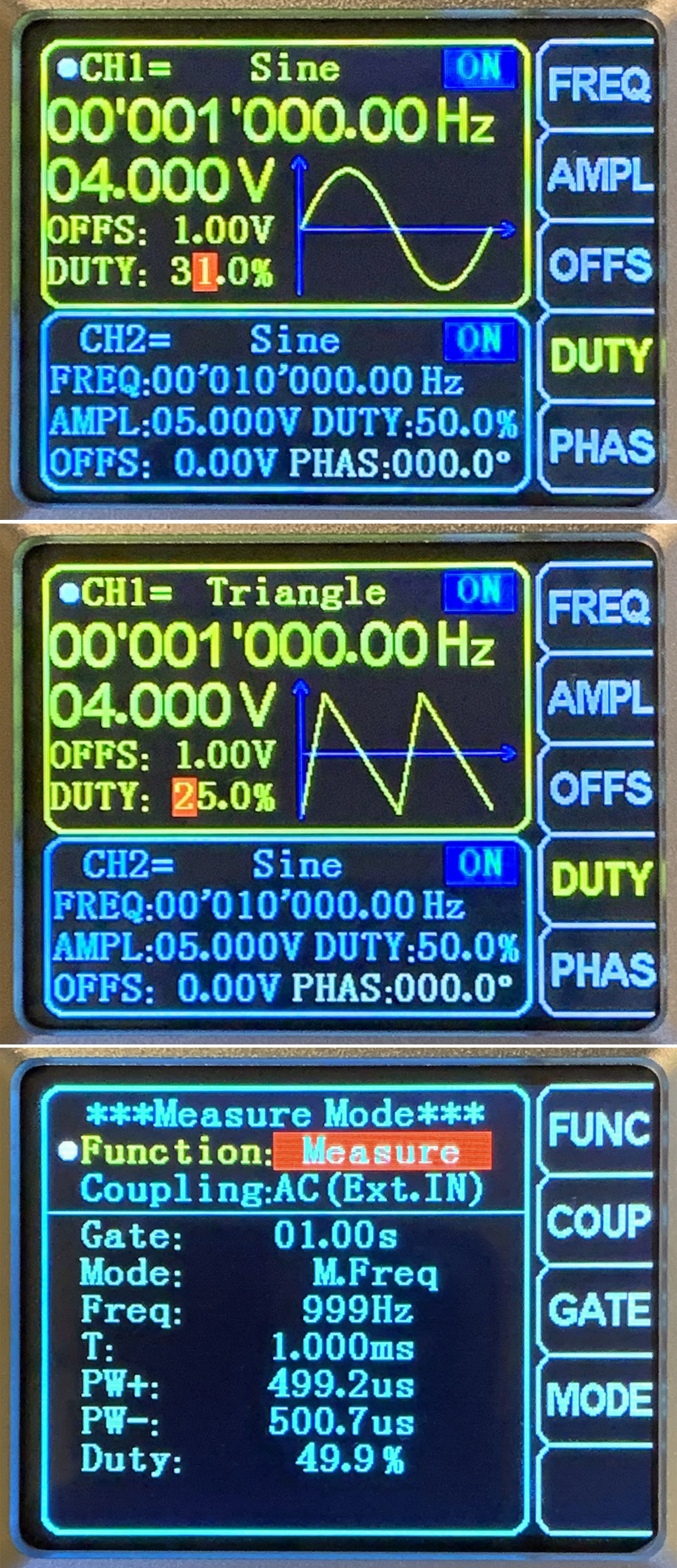
The pulse duty factor is useful for the pulse output function and is also interesting when applied to the triangle waveform generator (centre). The output signal is triangular when the duty cycle is set to 50%. Adjusting the duty cycle changes the waveform to produce a sawtooth.
The frequency counter (below) appears when the ‘MEAS’ button is pressed. For testing I just measured the 1 kHz calibration signal output from my scope. The displayed value wanders between 999 Hz and 1 kHz, indicating that the signal may not be completely symmetrical.
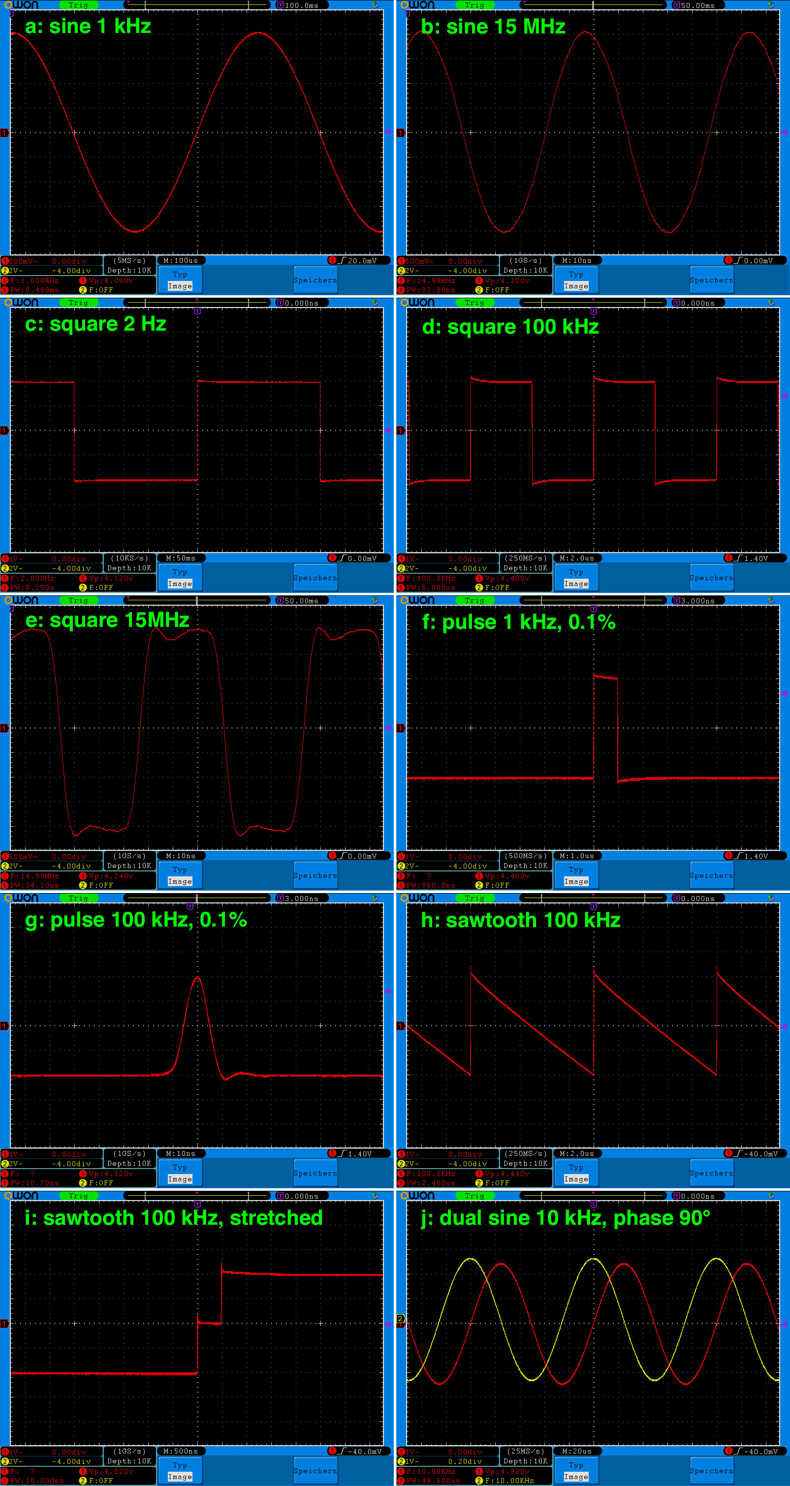
The most important thing about a signal generator is the quality and the range of different waveforms generated. Figure 5 shows a variety of output signals produced by the JDS2915. The signals have a set amplitude of 4 VPP and were measured using a 100 MHz scope which provides a single-channel sampling rate of 1 GS/s.
Sinewave
The sinewave in Figure 5a looks very clean. If you look more closely however, small steps in the waveform are evident. This turned out to be a feature of the input 8-bit A/D converter of my scope rather than the signal generator output signal. The 14-bit D/A of the generator offers much finer resolution. I checked this by expanding the X and Y axes: the steps only show up when amplified 100 times! Even at 15 MHz, the signal from Figure 5b still looks relatively pure with only slight visible distortion. The output signal amplitude remains relatively constant even at this frequency.
Squarewave
Figure 5c shows a squarewave signal at 2 Hz (DC-coupled). The value of 4.12 V displayed is due to the uncalibrated state of my scope’s input amplifier. In fact, it's 4.03 V! At 100 kHz, there are slight overshoots at the rising and falling edges shown in Figure 5d — not nice, but acceptable. At 15 MHz in Figure 5e limitations in the bandwidth of the analogue output amplifier are noticeable — but the signal still roughly approximates to a square wave.
Pulse
A pulse with a duty cycle of 0.1% at 1 kHz is shown in Figure 5f. The pulse has a width of 980 ns which represents an error of 2%. At frequencies above 100 kHz, the shortest pulse generated with a duty cycle of 0.1% is no longer a step but has a characteristic pulse shape with all its higher frequency components filtered out by the amplifier bandwidth. The pulsewidth is about 10 ns measured at half the peak output voltage level (Figure 5g). At frequencies above 1 MHz, the output signal amplitude becomes lower and drops to around 2 V at frequencies over 10 MHz. This is not surprising, since the generator's sampling rate of 266 MHz gives a resolution of just under 4 ns. In contrast to information on the data sheet, you can generate pulses at a repetition rate of up to 15 MHz.
Triangular
Figure 5h shows a 100 kHz triangular output signal that with its duty cycle ‘DUTY’ adjusted to 0.1% so that effectively a sawtooth waveform is output. Slight overshoot is evident on the rising edges. If you expand the horizontal timebase by five (Figure 5i), you can see steps in the rising edge. With a duty cycle of 0.0%, these steps disappear completely to give a clean sawtooth waveform.
Phase shifting
It’s useful to have two independent output signals, locked together but with an adjustable phase shift. The waveforms shown in Figure 5j are of two 10 kHz waveforms (at 5 VPP) phase-shifted by 90 ° relative to one another. If your scope has X-Y inputs you can use the phase-shifted signals to draw Lissajous patterns on the screen.
Conclusion
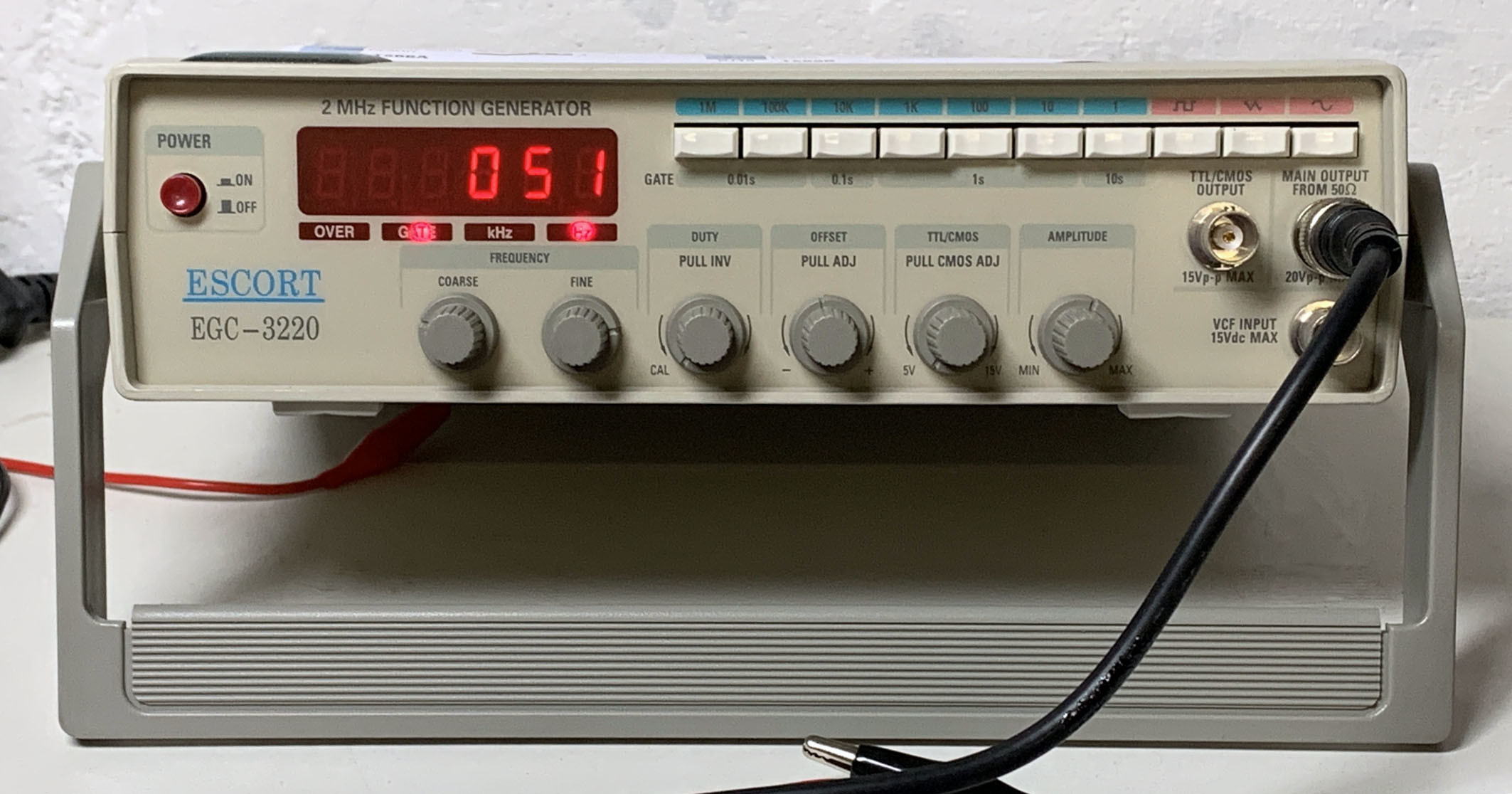
The one aspect of this unit’s design which niggles me slightly is the case. An enclosure made of (sufficiently thick) aluminum profile has got to be more robust and offer better electrical shielding and heat dissipation than one made of plastic. For me the unit, at 450 g, is however just too light, especially when compared to my old function generator (Figure 6), which weighs in at 2.5 kg (thanks mostly to its power transformer). It doesn’t slide across the bench top when I press any of the buttons. As far as the layout goes I would prefer to have the BNC sockets mounted on the front panel — but maybe your needs are different and the socket positions are an advantage.
Technically there is little to complain about with this signal generator with its built-in frequency counter. The signals are surprisingly clean — a big improvement on what I get out of my old generator. A unit offering a wider bandwidth will always have an advantage but in practice I personally hardly ever need a signal frequency higher than 10 MHz and remote control via a PC is a bonus. In this price bracket you wouldn’t really expect a LabView driver function to be included. In general: for just under €100 (for Elektor members) this function generator delivers an excellent price/performance ratio.
Want more great Elektor content like this?
Then take out an Elektor membership today and never miss an article, project, or tutorial.
Discussion (0 comments)