
My Journey into the Cloud (13): a small sensor board
December 8, 2016
on
on
In the last installment of this series I ported my mini-library for publishing MQTT messages to the Pretzel board which has an ATmega328 and an ESP8266 Wi-Fi module on board. The ATmega is easily programmable via the Arduino IDE and it controls the ESP8266 using simple ASCII commands for operations such as: login to a Wi-Fi network, establish a connection with a TCP server and send characters to it. The functions in my Mini-Arduino-TCP library (TCPClient_Connect, TCPClient_Close, TCPClient_Send) contain the ASCII commands sent to the ESP8266. For the commands in the rudimentary MQTT library functions I could almost use their equivalent in the PC version unchanged, they are both based on the TCP-Library.
For testing I will use a really simple application. When power is applied to the system the ESP8266 first logs in to my home Wi-Fi network and an LED on the board lights up. After pressing a button (which I added via a plug in board) the ESP8266 using TCP, connects to the HiveMQ-Testserver in the Cloud. The MQTT-CONNECT command is then sent followed by the MQTT-PUBLISH command via TCP. The MQTT message that I send is the text ‘Button’ (followed by a count value) with ‘/ElektorMyJourneyIoT/TestTopic/test’ as the Topic. The results can be checked with an MQTT client of your choice.
When I resumed work on this topic two weeks ago I didn’t have much luck to begin with. I quickly concluded that the test server’s IP address must have changed. By declaring the URL string ‘broker.hivemq.com’ instead of the specific IP address ‘52.29.193.216’ in the Arduino sketch (and my test client for the PC) we were up and running again.
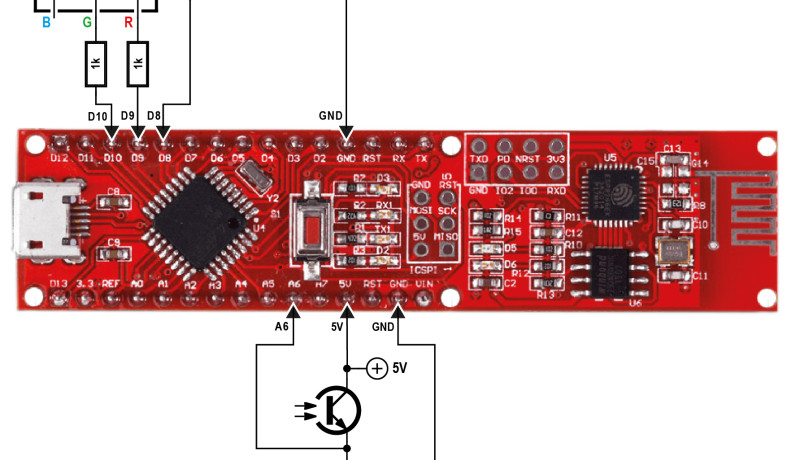
A notable absence in my implementation is any error handling mechanism. The LED lights up even if the SSID and password (hard coded in the Arduino sketch) supplied are wrong so that the board may not even be able to log in to my Wi-Fi network. I swapped the single color LED for an RGB type of LED supplied in the Maker-Kit; this gives me the chance to signal red when an error is detected and green when everything’s OK. In the handbook that comes with the Pretzel board it describes a practical routine in the bundled SoftwareSerial library which can be used to read ASCII data received from the ESP8266. Amongst other characters this module will send ‘ERROR’ when a command form the ATmega is not successfully executed and ‘OK’ when successful. Using the statement:
Boolean success = esp8266.findUntil(“OK“, “ERROR“);
instructs the ATmega to wait until either ‘OK’ or ‘ERROR’ is received from the ESP8266 (or a predefined timeout period expires). This is a relatively elegant mechanism compared to my earlier quick and dirty delay command used in my first version of the program.
Or so I thought… I included this function in the sketch setup routine so that I would be able to identify errors occurring during Wi-Fi log in. What followed was a few hours of frustration, the LED continued to remain green whichever random password I used. The ESP8266 must be continually sending ‘OK’ after it receives the command to login. I eventually found out that processing of an acknowledgement to a previous command did not have time to finish before I sent the new command. A small delay command solved the problem.
Now we are getting closer to our goal of a standalone sensor board. There is a photo-transistor sensor supplied in the Maker-Kit, using it in a network with a resistor we can produce a voltage level connected at pin A6 of the Pretzel board where it can read and converted to a digital value. The pushbutton can be used here. You can switch between ‘test’ and ‘sensor’ mode which is indicated by the blue LED D3 on the board. When power is connected to the board the ESP8266 logs into the Wi-Fi network using the network credentials which you need to declare hardcoded in the sketch. The RGB LED will now light up green if this was successful. By pressing the pushbutton you can switch to ‘Sensor’ mode. The board continuously reads brightness values and converts them into 10-bit digital values using the built-in ADC. Each string of hex characters are then sent via MQTT under the topic given above to the test server. My function
void SendValueOverMQTT(int TenBitValue)
is still somewhat clumsy: first it closes the TCP link and then re-establishes it. For this process I implemented an error handler with an indicator. When the TCP link fails to connect the RGB LED lights up red. When the link is successful it lights up yellow (both red and green LEDs lit) then the MQTT commands can be sent. The RGB-LED then goes green (so far I haven’t implemented an MQTT error handler but hey, I need to hold something back for the next installment ;-) ). The process repeats with a new measurement value. In test mode the process begins again by pressing the pushbutton (hold it down until LED D3 turns off). In this mode you can control the ESP8266 ‘manually’ using a terminal emulator program.
As always the code is included in the download together with a modified version of my MQTT test client for the PC which receives the measurement data values (enter ‘TestTopic’ in the textbox ‘Topic to subscribe’). I have not made any attempt to modularize the code, introduce any levels of abstraction or tidy it up, that way it’s easier to follow the development from previous versions. We will of course get round to doing this eventually, that way we can more easily port this small reference application to other types of board.
Stay tuned for the next installment!
For testing I will use a really simple application. When power is applied to the system the ESP8266 first logs in to my home Wi-Fi network and an LED on the board lights up. After pressing a button (which I added via a plug in board) the ESP8266 using TCP, connects to the HiveMQ-Testserver in the Cloud. The MQTT-CONNECT command is then sent followed by the MQTT-PUBLISH command via TCP. The MQTT message that I send is the text ‘Button’ (followed by a count value) with ‘/ElektorMyJourneyIoT/TestTopic/test’ as the Topic. The results can be checked with an MQTT client of your choice.
When I resumed work on this topic two weeks ago I didn’t have much luck to begin with. I quickly concluded that the test server’s IP address must have changed. By declaring the URL string ‘broker.hivemq.com’ instead of the specific IP address ‘52.29.193.216’ in the Arduino sketch (and my test client for the PC) we were up and running again.
A notable absence in my implementation is any error handling mechanism. The LED lights up even if the SSID and password (hard coded in the Arduino sketch) supplied are wrong so that the board may not even be able to log in to my Wi-Fi network. I swapped the single color LED for an RGB type of LED supplied in the Maker-Kit; this gives me the chance to signal red when an error is detected and green when everything’s OK. In the handbook that comes with the Pretzel board it describes a practical routine in the bundled SoftwareSerial library which can be used to read ASCII data received from the ESP8266. Amongst other characters this module will send ‘ERROR’ when a command form the ATmega is not successfully executed and ‘OK’ when successful. Using the statement:
Boolean success = esp8266.findUntil(“OK“, “ERROR“);
instructs the ATmega to wait until either ‘OK’ or ‘ERROR’ is received from the ESP8266 (or a predefined timeout period expires). This is a relatively elegant mechanism compared to my earlier quick and dirty delay command used in my first version of the program.
Or so I thought… I included this function in the sketch setup routine so that I would be able to identify errors occurring during Wi-Fi log in. What followed was a few hours of frustration, the LED continued to remain green whichever random password I used. The ESP8266 must be continually sending ‘OK’ after it receives the command to login. I eventually found out that processing of an acknowledgement to a previous command did not have time to finish before I sent the new command. A small delay command solved the problem.
Now we are getting closer to our goal of a standalone sensor board. There is a photo-transistor sensor supplied in the Maker-Kit, using it in a network with a resistor we can produce a voltage level connected at pin A6 of the Pretzel board where it can read and converted to a digital value. The pushbutton can be used here. You can switch between ‘test’ and ‘sensor’ mode which is indicated by the blue LED D3 on the board. When power is connected to the board the ESP8266 logs into the Wi-Fi network using the network credentials which you need to declare hardcoded in the sketch. The RGB LED will now light up green if this was successful. By pressing the pushbutton you can switch to ‘Sensor’ mode. The board continuously reads brightness values and converts them into 10-bit digital values using the built-in ADC. Each string of hex characters are then sent via MQTT under the topic given above to the test server. My function
void SendValueOverMQTT(int TenBitValue)
is still somewhat clumsy: first it closes the TCP link and then re-establishes it. For this process I implemented an error handler with an indicator. When the TCP link fails to connect the RGB LED lights up red. When the link is successful it lights up yellow (both red and green LEDs lit) then the MQTT commands can be sent. The RGB-LED then goes green (so far I haven’t implemented an MQTT error handler but hey, I need to hold something back for the next installment ;-) ). The process repeats with a new measurement value. In test mode the process begins again by pressing the pushbutton (hold it down until LED D3 turns off). In this mode you can control the ESP8266 ‘manually’ using a terminal emulator program.
As always the code is included in the download together with a modified version of my MQTT test client for the PC which receives the measurement data values (enter ‘TestTopic’ in the textbox ‘Topic to subscribe’). I have not made any attempt to modularize the code, introduce any levels of abstraction or tidy it up, that way it’s easier to follow the development from previous versions. We will of course get round to doing this eventually, that way we can more easily port this small reference application to other types of board.
Stay tuned for the next installment!
Read full article
Hide full article

About Jens Nickel
Jens Nickel is ElektorMag’s Editor in Chief. His interests include programming, home automation, and the IoT, and he enjoys the production of electronic music. Watch him on <em>Elektor Lab Talk</em>. >>
Discussion (0 comments)