
Remote Sensing with Connection Loss Detection Using nRF24L01+ Modules
on
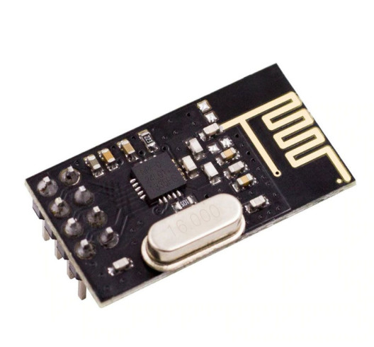
Nordic Semiconductor's nRF24L01+ RF modules (Figure 1) are interesting, low-cost solutions for wireless two-way communication. The modules have a serial peripheral interface (SPI) bus that enables configuration and control via a microcontroller. Many examples of projects using Arduino boards in combination with these RF modules can be found on the Internet.
With the project described here, I want to add an extra feature that uses the two-way communication to detect the loss of communication between the transmitter and the receiver. It’s a bit odd to talk about a transmitter and a receiver when using two-way communication, since modules act as a transmitter and as a receiver at the same time. But for clarity we label one module as the transmitter because its main task is to transmit the state of a (PIR) sensor to another module, which receives the data for further processing.
The ability to detect the loss of communication is very useful for remote sensors, because when there is no communication, data can get lost without noticing. It is also useful when installing the sensor to check if both nRF24L01 RF modules actually “see” each other and are not out-of-range.
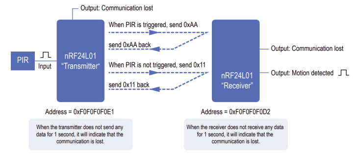
In Figure 2 you can see an overview of the project and how both nRF24L01 modules communicate with each other — and how the detection of loss of communication is implemented.
Circuit Diagrams
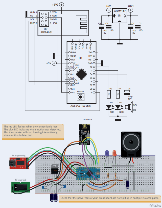
Let us begin with the schematic of the transmitter (Figure 3). The nRF24L01 needs to be powered with 3.3 V, but the I/O pins of the nRF24L01 are 5-V tolerant. So, connecting the nRF24L01 SPI bus directly to a 5-V Arduino Pro Mini is no problem.
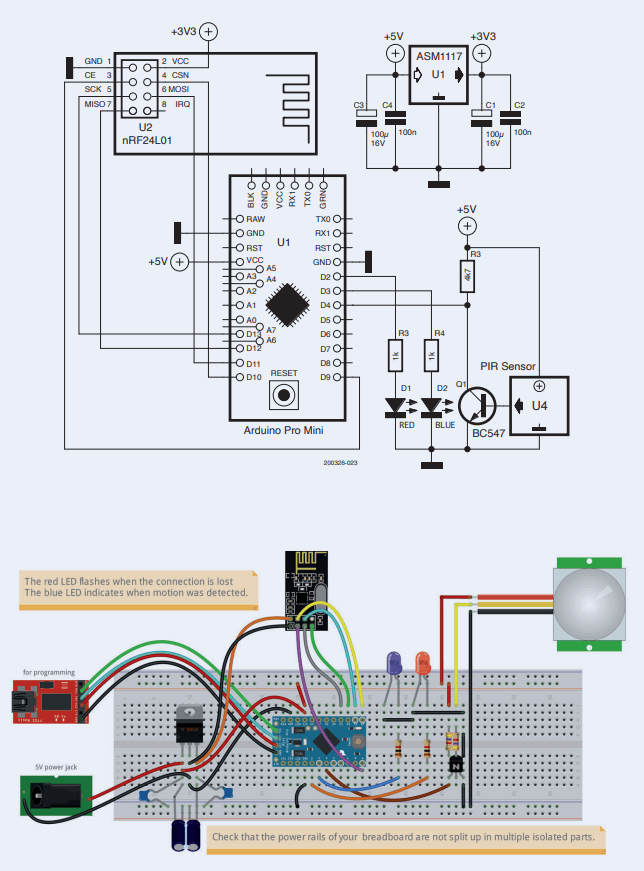
The power supply bypass capacitors should be placed as close as possible to the Arduino and the nRF24L01 module, respectively, to suppress all the switching noise coming from these chips. This is often overlooked in Arduino projects and can cause all kind of unexpected problems. It is also good practise to use multiple bypass capacitors in parallel with different values (e.g., C1 = 100 µF and C2 = 100 nF). Electrolytic capacitors are not as effective at higher frequencies as ceramic capacitors or polypropylene film capacitors. By putting different capacitor types in parallel, a more effective filter is created over a wider frequency range.
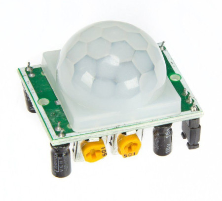
The PIR sensor (Figure 4) is connected to D4 of the Arduino. When the PIR sensor requires a different voltage than 5 V, this can be accommodated. Q1 acts as an (inverting) voltage level translator in case sensors are used that have, for example, a 3.3 V or lower output voltage. This way you can connect other types of sensors without changing the hardware. When the PIR sensor has a 5 V level output, Q1, R4 and R3 can be omitted and the PIR sensor output directly connected to pin 4 of the Arduino Pro Mini. When doing so, the Arduino sketch needs to be adapted, so the trigger input is high active instead of low active: #define TRIGGER_ACTIVE_LEVEL 0 /* 0 = low active, 1 = high active */ .
The red LED (D1) will flash when the connection between the transmitter and the receiver is lost. When the connection is restored, the red LED will stop flashing and everything will work as normal again.
The blue LED (D2) indicates that the PIR sensor detects motion. This trigger event will be send over to the receiver as a trigger code byte. When the PIR sensor does not detect motion, then a live beat code will be send to the receiver. This way the receiver knows if there is a motion trigger or not.
The following code will show the livebeat code and trigger code defines:
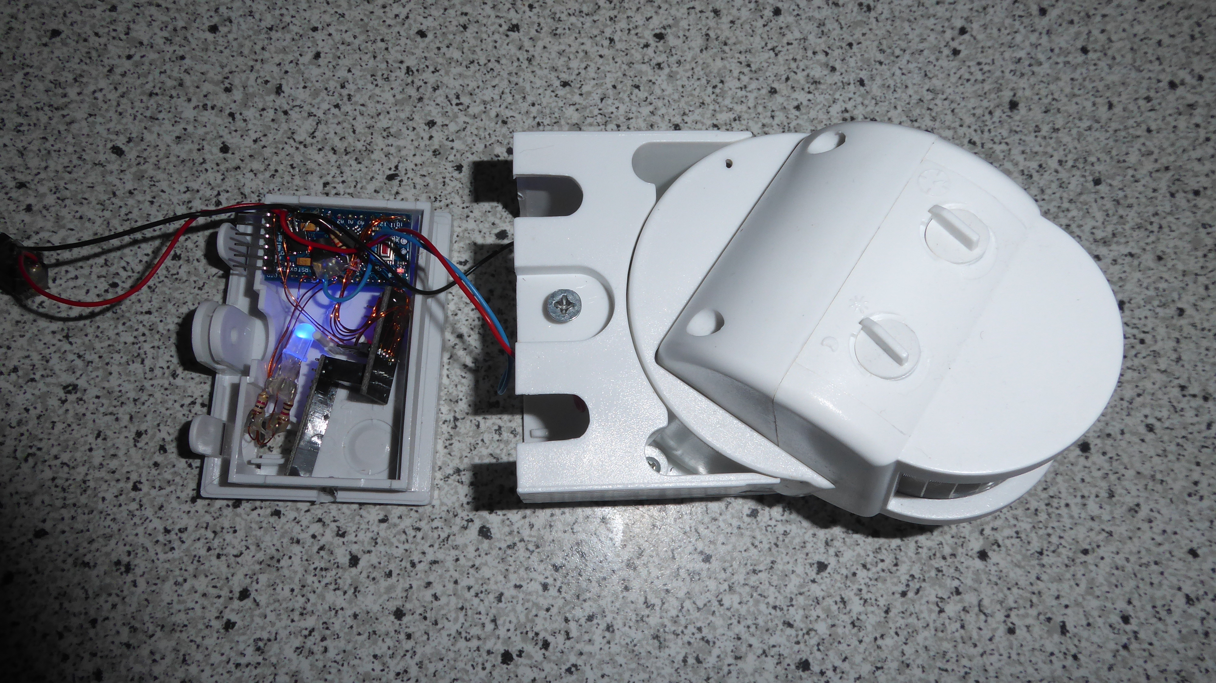
Figure 5 shows the Transmitter unit with the PIR sensor.
Receiver
The receiver (Figure 6) will send the same code that it received from the transmitter back to the transmitter as an acknowledge. Because of this continuous communication between the transmitter and receiver, both can easily determine when the connection is lost.
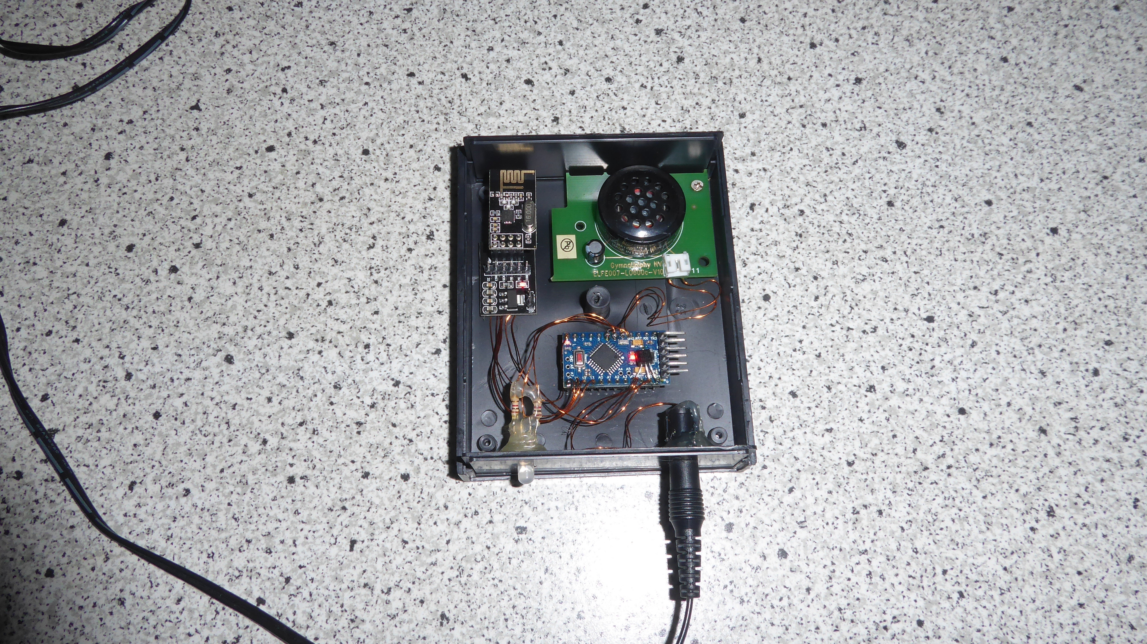
The receiver circuit (Figure 7) is almost identical to the transmitter circuit. In the receiver, the red LED (D1) will start flashing when the connection is lost and the Arduino will send a tone to the speaker using the tone (x, y) command, with x = frequency and y = duration. The speaker is an 8 Ω version and is connected to the Arduino via an electrolytic capacitor. The higher the value of the capacitor, the higher the speaker volume will be. For a 50 Hz tone for 150 ms the following code is used:
I’ve chosen for a low-frequency tone because that is less annoying/disrupting than higher tones. The blue LED (D2) indicates when motion is detected. You can connect a relay to this output via a transistor to power on/control any other device when motion is detected.
Discussion (13 comments)