
RGB Stroboscope with Arduino: A Colourful Adaptation of a Useful Instrument
on
In days gone by, before the advent of modern electronics under the bonnet, the stroboscope was used to adjust the ignition timing of engines. These days, this is rarely necessary — in reasonably modern vehicles, the ignition timing is regulated by an engine control unit (ECU) aided by countless sensors.
The Stroboscope
Everything used to be different – not necessarily better, but still different. Not all that long ago, there was still reason enough to get under the bonnet of a vehicle to tinker, make repairs and perform adjustments. Thanks to modern computer-based design methods, it is now possible to fit all the components under the bonnet so compactly and close together that even replacing a simple lamp is a major challenge. And, of course, computers in the form of a large number of interconnected microcontrollers have also found a place under there too.
Let’s take a walk down memory lane, however, to the 1970s or 1980s. For proper operation of an internal combustion engine (petrol engine), the spark plugs of all the cylinders have to generate sparks at precisely the right time. This was handled by the distributor (a mechanical contraption, which was perilously sensitive to moisture in some vehicles), that had to be precisely synchronized with the engine. That’s where the stroboscope – or timing light as it was also called back then – came into play.
An old-fashioned distributor had the same number of contacts as the number of cylinders in the engine and, each time a contact opened, the electrical energy stored in the ignition coil produced a spark at the tip of the spark plug. In turn, this ignited the fuel-air mixture in the cylinder. That’s what made the engine run.
The stroboscope used to adjust the timing had a xenon or neon flashlamp and a trigger cable. The trigger cable (with an inductive sensor) was attached to the reference spark plug cable so that each time the reference spark plug fired, the flash tube was triggered and produced a very short flash of light. There was a white mark (a narrow stripe) on the crankshaft pulley with a matching fixed mark on a sort of angle bracket above the pulley. These two marks were supposed to be exactly aligned to each other when the reference spark plug fired, and the stroboscopic effect of the timing light made it look like this moving mark was standing still. If the moving mark on the crankshaft pulley was not aligned to the fixed mark, but instead offset to the left or to the right, this indicated that the distributor required adjustment.
Triggering? Who Needs It?
In the application described above, the stroboscope is synchronized by a trigger signal with the rotary motion being measured. However, a trigger signal is not always necessary.
If you want to measure the engine speed (RPM) using a non-synchronized stroboscope, you have to adjust the frequency of the light flashes so that the mark on the pulley appears to be practically stationary and can be seen in only one place. If several nearly stationary marks can be seen at the same time, this means that the flash rate is a multiple of the RPM, or the RPM is a multiple of the flash rate.
If the pulley is turning clockwise and the mark is drifting in the clockwise direction, the flash rate is a bit too low. Each flash comes too late, so the mark appears to move in the direction of rotation. If the pulley is turning clockwise and the mark is drifting in the anticlockwise direction, the flash rate is a bit too high, so each flash must be a bit too early.
In this way you can measure the RPM by adjusting the flash rate of the stroboscope so that only one stationary mark is clearly visible. Each flash must be short enough to produce a distinct reflection (in other words, a distinctly visible mark). If the flash duration is too long compared to the flash rate, the mark will look ‘smeared’.
Let’s Have Some Fun with This
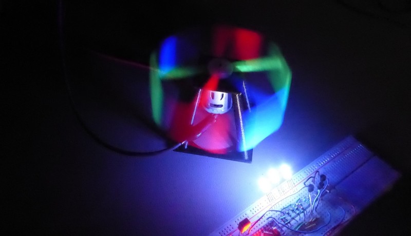
What happens if we generate several flashes at the same rate, but with different colors and a phase shift between the individual flashes? And what will we see if we also use a rotating white object and vary the frequency, phase shift, and duration of the different colored flashes?
This is not difficult to achieve with the aid of a microcontroller, so there’s nothing stopping us from trying this. We can use an RGB LED for the different colored flashes or, better yet, three separate LEDs to produce brighter flashes. To control the flash rate, phase shift, and flash duration, we can use an Arduino Pro Mini as it has enough I/O to work with and is more than fast enough for what we have in mind. The LEDs, as you might expect, can be driven by pulse-width modulated (PWM) signals.
We could use three dedicated PWM modules of the Arduino Pro Mini, but they operate from three different timers. That makes it more difficult to synchronize them and to program the phase shifts. What’s more, we need relatively low-frequency PWM signals, so a resolution of 16 bits is far too much. Software-generated PWM signals (softPWM) are perfectly satisfactory for our purposes. With softPWM, the signals are output on normal digital I/O pins. These are set and reset using a counter that generates an interrupt each time it reaches a specific state. This allows us to configure an interval that is short enough to adjust the pulse-width or phase shift of the PWM signals with sufficient precision.
Putting It Into Practice
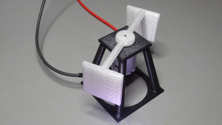
To implement the concept described above, the author used a 12 V DC motor (Velleman part number MOT3N) and designed a small frame for it. The motor turns a sort of propeller with two vertical blades that act as reflectors. Both parts were made with a 3D printer and the relevant files are available at the end of this article. Figure 1 and Figure 2 show what they look like.
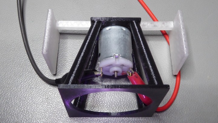
Note that the no-load speed of the motor used by the author is around 11,500 rpm, which is much too fast for the 3D-printed propeller. The first time the author tested this setup, parts were literally flying past his ears. This is naturally a bit risky, so it is a good idea to wear safety glasses or goggles. You have been warned!
For this reason, the author operated the motor from a DC voltage of approximately 3 V. This voltage can be adjusted to synchronize the motor speed to the flash rate. With a 3 V supply voltage, the motor speed is approximately 2100 rpm, equivalent to a frequency of 35 Hz. The propeller has a symmetrical structure with two reflecting blade surfaces, which makes balancing a little easier. Because of this, the flash rate has to be twice as fast (70 Hz) corresponding to a period of approximately 14 ms.
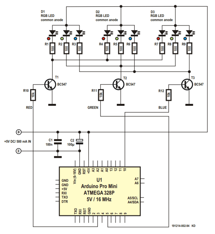
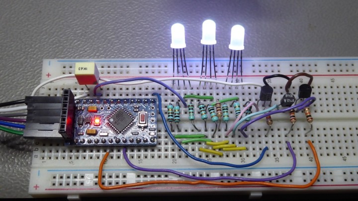
But first, let’s look at the circuitry. The schematic diagram shown in Figure 3 is a model of simplicity. The three RGB LEDs are switched on and off by modest driver transistors under the control of the Arduino Pro Mini. The supply voltage for all of this is 5 V DC, with a current consumption of approximately 500 mA.
No PCB has been designed for this, but you can build everything on a breadboard in next to no time. The author’s setup is shown in Figure 4.
The stroboscope timing is controlled using a timer interrupt that is triggered every 100 µs. This 0.1 ms interval is therefore the resolution for adjusting the flash rate and proved to provide adequate control capability for shifting the ‘stationary’ image of the propeller.
// Setup 16bit timer1 in normal operation with interrupt at 100us
// 16MHz/1 = 6.25ns. So to get 100us we need to let the timer count 1600 ticks.
TCCR1A = 0;
TCCR1B = _BV(CS10); //prescaler divide by 1
TCNT1 = 0xFFFF - 1600; // overflow is at 65535 = 0xFFFF
TIMSK1 = _BV(TOIE1); // overflow interrupt
TCNT1 = 0;
sei();
}
ISR (TIMER1_OVF_vect)
{
TCNT1 = 0xFFFF - 1600; //100us interrupt
...
The flash period is hard-coded in the software and set to 144, which is the number of timer interrupts between two successive flashes. This means the period is 144 × 100 µs = 14.4 ms. The flash duration for each LED is set to a fixed value of 8, corresponding to 8 × 100 µs = 800 µs. The duty cycle (mark/space ratio) is therefore 800 µs / 14.4 ms = 5.5%.
TSoftPwm Pwm[] = {TSoftPwm(ID_RED, 0, 8, STROBE_PERIOD),
TSoftPwm(ID_GREEN, 0, 8, STROBE_PERIOD),
TSoftPwm(ID_BLUE, 0, 8, STROBE_PERIOD)};
This duty cycle gives a nice, sharp image once the motor speed is suitably adjusted.
The circuit plus software is not a finished project. Instead, the author intends it to be a proof of concept and has therefore not provided a nice user interface or any other fancy features. The available software demonstrates what can be done by playing with the parameters of flash rate, flash duration, and phase difference. The software is extensively and clearly commented, so there’s no need to describe it in detail here.
Of course, a non-synchronised stroboscope leaves room for improvement. In principle, it shouldn’t be that difficult to mount a small light beam interruption sensor next to the propeller and use the sensor signal to trigger the stroboscope. However, we’ll leave that as a project for our interested readers.
(191214-03)
Editor's note: The author has posted two videos on YouTube where you can admire the operation of the stroboscope and view the interaction between the LED control signals on an oscilloscope screen. The project is also available on the Elektor Labs site.
Discussion (1 comment)