Brushless DC motors, or BLDCs, have brought some great new applications to market, from drones and e-scooters to electric vehicles. But, unlike brushed DC motors, integrating them into an application is quite complicated. So how do you commutate a BLDC motor?
Almost everyone has controlled a small DC motor. All it requires is a power source, like a battery, and the rotor whizzes into life. If you have a bench power supply, you can even control the speed by adjusting the voltage. But this is impossible with a brushless DC motor (BLDC) due to how they are constructed.
Brushed DC motors are simple to use because the commutation method is mechanical. The position of the carbon brushes in relation to the commutator ensures that the appropriate coils are powered at precisely the right moment with respect to the magnetic field generated by the permanent magnets.
BLDC motors, on the other hand, require electronic commutation. The wiring for each coil is brought out of the casing, and the developer is responsible for powering them in the correct order.
Subscribe
Tag alert: Subscribe to the tag BLDC Motor and you will receive an e-mail as soon as a new item about it is published on our website!
Motor Structure
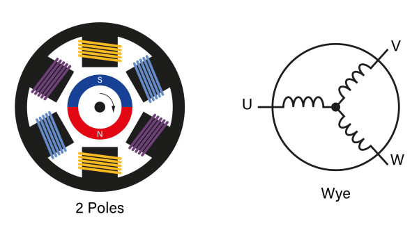
Before tackling the electrical control, its necessary to understand the mechanical construction of a brushless DC motor. A BLDC motor typically has three wires; in many articles on their use, they are named U, V, and W. The permanent magnet is found affixed to the rotor, while the coil windings (stator) are attached to the motor housing.
A basic single pole pair BLDC motor and the Wye, Y, or star winding used. (Source: Monolithic Power)
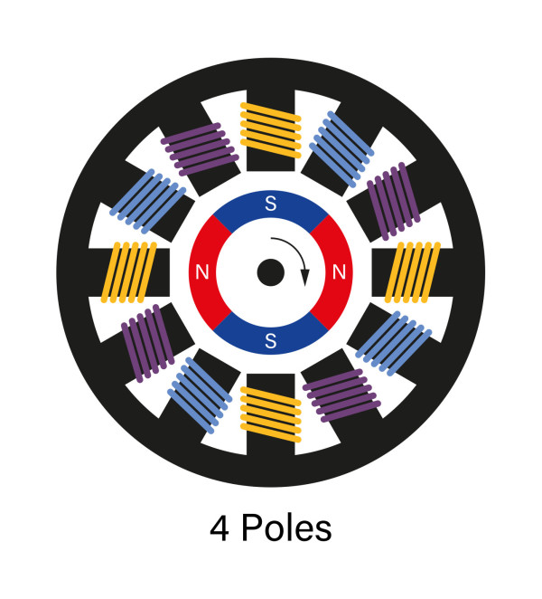
An important aspect of the motor’s design is the number of north/south poles on the rotor, typically termed pole pairs. Most motors have two pole pairs (four poles), although the number can rise to three, four, or be as low as one (two poles). Fewer pole pairs mean the rotor can turn more quickly, but the torque at low speeds is lower than if there are more pole pairs. More pole pairs improve torque at low speeds, but the top speed may be lower than a motor of comparable size.
A two pole pair (four pole) BLDC motor. (Source: Monolithic Power)
Depending on the documentation, the stator winding will be connected in Wye, Y, or star configuration, all terms for the same thing. Some motors also provide a fourth wire connected to the point where the three coils meet. This can be used in some circuits as part of the motor control approach but, during operation, should be sitting at half the voltage applied across the two active phases and should be left floating.
There are also many different variants of BLDC motors designed to meet the needs of specific applications. For example, for drones and model aircraft, outrunner motors are popular. Here the stator is in the middle, and the rotor and its permanent magnets are on the outside. Cooling can improve as a result, and the higher inertia of the design helps maintain a stable motor speed. Despite the differences, the control approach remains the same.
Outrunner BLDC motors place the rotor's permanent magnets on the outside with
the stator coils in the center. Such motors are popular in drones and RC model aircraft.
It is important to note that an incredible number of designs and construction materials are used for BLDC motors, so consider the above as starting guidance only. Quality motor manufacturers provide a wealth of information on their websites regarding torque, maximum speed, pole pairs, and factors like size, volume, and power rating.
Commutating the Motor
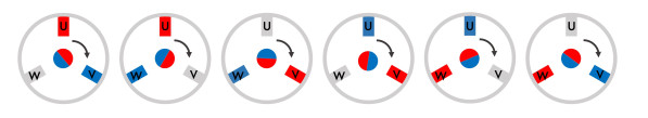
Because the rotor is the part with the permanent magnetic, it is the job of the design engineer to create a rotating magnetic field that the rotor follows. This means the stator coils must be energized in a specific order. Each stator needs to be energized once as a north pole and once as a south pole. With three stators, this means we have a sequence of six steps to implement electronic commutation.
The rotor (center) follows the magnetic field in six steps generated by the stators U, V, and W.
Red is the north pole, blue is south.
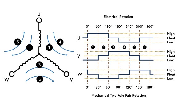
Electrically speaking, in each phase, we need one coil connected to the supply, one connected to ground, and one left open.
Current flows through the BLDC motor's Wye configuration as shown here (left),
while the diagram shows when the phases are connected to high, low, or left floating.
The difference between electrical and mechanical rotation is also shown.
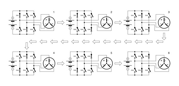
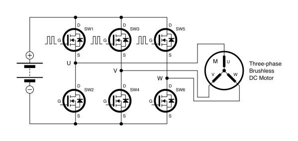
To implement this, a three-phase bridge circuit is used. Consisting of six MOSFETs, a microcontroller or a dedicated integrated BLDC motor driver chip controls them. Like the H-bridge for controlling brushed DC motors, there is a risk of a short circuit. Thus, when writing software for a microcontroller, care must be taken to ensure the high and low side of one leg aren’t turned on simultaneously.
Because the coils have a very low resistance, leaving a coil powered for any length of time is also risky. This can occur when a debugger with a microcontroller is used and a breakpoint is reached. Some microcontrollers targeting BLDC motor control applications can disengage their control pins when the debugger halts the microcontroller.
Simplified circuit diagram showing how the BLDC motor phases are controlled using
a three-phase bridge. The switches are typically implemented using MOSFETs or IGBTs.
This is where things start to get a little more complicated. One electrical rotation following these six steps does not always equal one mechanical rotation! The mechanical and electrical rotation are the same if the motor has a single pole pair, as in the diagrams above. One electrical rotation equals half a mechanical rotation for a motor with two pole pairs. With four pole pairs, you’re down to a 90° mechanical rotation. It is important to consider this when developing software. Firstly, every time you complete an electrical rotation, you must factor in this difference if your software reports mechanical rotations in RPM (rotations per minute).
Another important consideration is the load on the processor. At 100 RPM, you have 600 ms (60 seconds ÷ 100) to execute the code for a single rotation of a single pole pair motor. For a four-pole pair motor, you need to be able to execute the same code in just 150 ms (a quarter of the time). At 1,000 RPM, this drops to 60 ms and 15 ms, respectively.
When your code for maintaining speed is also considered (typically a PID controller), the load on the processor can be exceptionally high and even limit the RPM the motor can achieve. This is why many microcontroller vendors offer devices dedicated to motor control, with peripherals that offload much of the complexity into hardware.
Subscribe
Tag alert: Subscribe to the tag motor control and you will receive an e-mail as soon as a new item about it is published on our website!
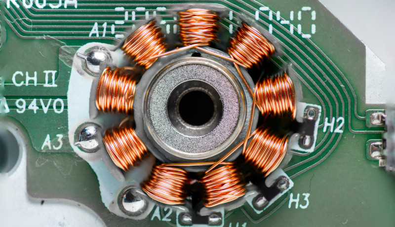
Getting the Order Right and at the Correct Time – Rotor Position Sensors
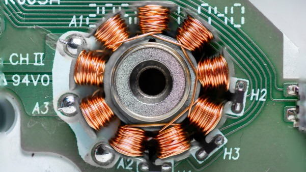
So, which coil pair do you engage first? Well, it’s a one-in-six chance of guessing correctly. To resolve this, many motors either have a rotor sensor or have provision for attaching one. At the low-cost end are Hall sensors. These typically provide a resolution of 60° or better (360° ÷ 6 for a single pole pair motor). At the top end are resolvers, an analog sensor that can provide sub-degree rotor angle feedback. Your microcontroller or integrated BLDC driver chip will read this sensor before engaging the first coil pair so that the current rotor angle is known.
Three Hall sensors, marked H1, H2, and H3, integrated into a compact BLDC motor.
The advantage of knowing the rotor position before engaging the coils is that it stops a sudden jerking of the rotor to match the position of the applied magnetic field. Of course, knowledge of the rotor position is critical throughout motor commutation, ensuring that the next correct pair of coils are engaged as the rotor rotates. The sensor’s feedback is also passed to the control algorithm, enabling speed to be maintained even as the load changes.
Controlling BLDC Motor Speed
With the rotor position clear and the ability to power the correct pair of stator coils at the correct moment, the next step is controlling the motor’s speed. This is done in exactly the same manner as with a brushed DC motor: by varying the voltage.
Referring back to the three-phase bridge circuit, the three upper MOSFETs are usually connected to microcontroller pins capable of producing a pulse-width modulated (PWM) output. At a low mark-space ratio, the voltage applied to the stator coils is low. As a result, the motor rotates slowly, and, using the feedback from the Hall sensor, the microcontroller changes the output signals to implement the six-step commutation process at the appropriate speed. As the voltage increases, so does the rotor speed and the rate at which the microcontroller works through the six commutation steps.
Note that applying a load to the rotor causes it to slow down unless a speed control algorithm (PID) has been implemented.
PWMs applied to the high sides of the three-phase bridge at the appropriate commutation
points enable control of the motor's speed.
More Advanced BLDC Control Approaches
Like everything in electronics, you can always refine control if you can find a way to manage the complexity! For example, a sensor on the rotor adds weight, makes the motor larger, costs money, and is an additional source of potential failure.
Instead, the back-EMF of the motor can be monitored using an analog-to-digital converter (ADC) that monitors the motor phases that are not being driven or connected to ground. This requires analog and digital filtering due to the noise in such circuits, placing further load on the processor. One issue with this approach is that a static rotor produces no back-EMF, thus it is challenging to determine the rotor angle at rest. However, some clever approaches and software algorithms can overcome this.
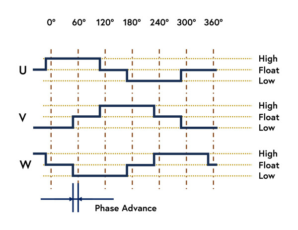
If you want to drive the motor faster than specified, this is also possible. Simply configure the commutation software to change to the next commutation step a little earlier than required, i.e., pre-empt the next commutation step. Termed phase advance in documentation, motors can achieve more than double the datasheet maximum RPM. However, this comes at a torque loss and electrical efficiency drop.
Moving to the next commutation step a few degrees earlier, known as phase advance, the motor's RPM
can be pushed beyond its datasheet limit. The penalty for this is a loss of torque and efficiency.
BLDC motors driven by six-step commutation also generate torque ripple, a slight unevenness in the rotation of the rotor. Clever methods used in the motor’s construction can help limit this, but this can be an issue for precision control systems or applications where audible noise must be kept to a minimum. If your processor is up to it, you can vary the PWM outputs so that a sine wave output is generated instead of generating a variable DC output to the stator coils. The sine wave’s amplitude determines the motor speed, and as the rotor speed increases, the sine wave frequency must increase to keep up.
Chips for BLDC Motor Control
Searching for appropriate silicon to implement BLDC motor control can be confusing, as there are many providers for different sections of the system. Companies like Microchip and Infineon offer microcontrollers dedicated to motor control. These are often supported by current, angle, and position sensors. Others focus on the connection between the microcontroller and the three-phase bridge. The MOSFETs used often require a significant amount of power to drive their gates, so vendors such as Elmos, Toshiba, and Monolithic Power (MPS) offer (pre-)drivers. Such devices also provide short circuit protection, dead time control, and even small linear regulators to power the microcontroller and other circuitry.
Infineon's MOTIX motor control kit includes motor controller, angle, and Hall
sensors, for a rapid start into the world of BLDC motors. (Source: Infineon)
Fully integrated solutions are also available from suppliers such as Melexis. Highly integrated, these chips offer sensorless motor control and often come with various tools to tune the controller to the chosen motor. Finally, companies like Enclustra offer FPGA IP (intellectual property) for motor control. This can be combined with Xilinx or Altera FPGAs and provides exceptional control and eases support for multiple motor use cases, as the limits of control no longer depend on the performance of a processor.
Elektor Magazine has been one of the leading sources of information on electronics for engineers, designers, start-ups and companies for 65 years. Our magazine is powered by an active community of electronics engineers – from students to professionals – who are passionate about designing and sharing innovative ideas.
For them, we publish hundreds of items a year, in formats such as articles, videos, webinars, and other learning formats. Our mission is to share knowledge in every possible way and inspire readers with the latest developments within the electrical engineering sector.
Thank you for your vote!
Leave further comments in the fields below.
Thank you for your vote!
If you wish to leave a comment with your rating, please first use the login below. If not, just close this window.

Discussion (28 comments)