
Small Circuits Revival (21): Cable & Conduit Locator
on
Cable & Conduit Locator
Idea: Elex Team
Apart from the risk of a (dangerous) electric shock and the near certainty of a very massive short circuit that is the consequence of drilling into a cable, the aftermath of this mishap is no fun either. In any case, the damaged cable has to be replaced – and that is already not nice when these are running neatly through conduit, but in other countries where the wires are often tidily hidden under the plaster work, this is a small catastrophe.
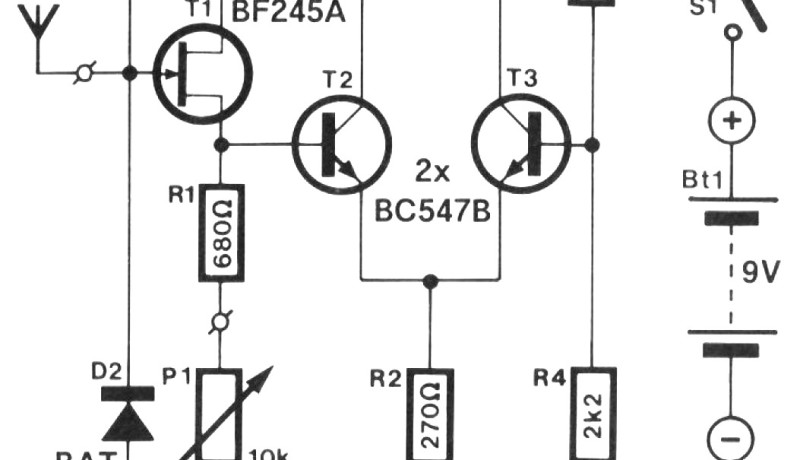
Prevention is better than cure, and that is why the better hobbyist makes use of a cable locator. But what to do on a rainy Sunday afternoon, when it is absolutely essential that a hole is drilled, but the DIY store is closed and you cannot quickly buy a cable locator? Then you build one yourself in a few minutes! Complicated it isn't, as the schematic of Figure 1 proves.
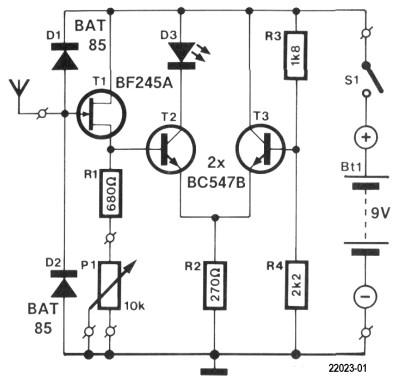
Three transistors and a few other bits – that's all. An "antenna" of sorts is connected to the gate of FET T1 (a solid piece of copper wire about 20 cm long); this picks up the ubiquitous 50 Hz or 60 Hz ‘mains hum’. The antenna is not loaded because of the very high input impedance of the FET. Diodes D1 and D2 (Schottky types BAT85) prevent the voltage at the gate from going too high.
The buffered antenna voltage is then available at the source of T1; the DC voltage level can be adjusted with P1. The source voltage goes to the base of transistor T2, which acts as a kind of comparator: it compares the voltage at its base with that at the emitter. And this latter voltage is generated by T3. With the component values shown here, the voltage at the top of R2 is about 4.25 V, and tconsequently T2 will start to conduct when its base voltage is higher than 4.95 V. LED D3 will then also light up.
P1 is used to adjust the circuit so that in the idle state the LED just remains off. The circuit can be built on a piece of prototyping strip board in a jiffy. And of course, this circuit also perfectly lends itself to doing your own experiments!
Discussion (3 comments)