
The µTracer tube tester kit. Part 3: a software interrupt
Running it
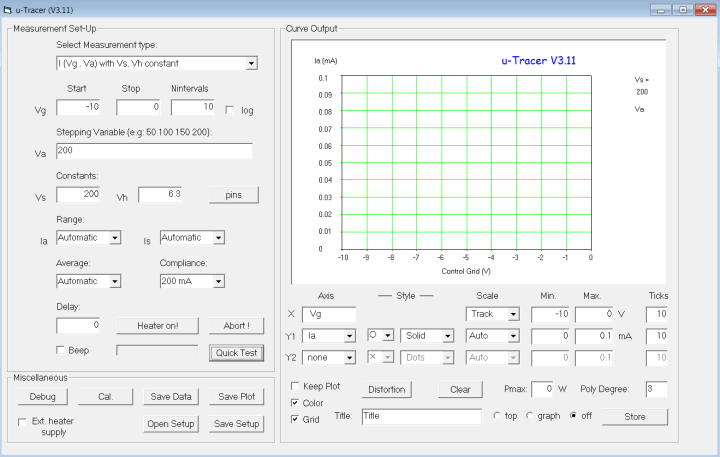
The moment of truth had arrived as far as dry swimming with the GUI is concerned: launching uTracer 3.11 through the Windows Start button. A typical VB look & feel screen pops up:
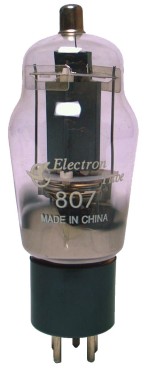
Happy to have come this far and learned a few things I was not in the least hesitant about entering some data and “see what happens”. Do remember though that the uTracer hardware is not connected at this point, in fact it’s not even completed and operational. But what can possibly go wrong by entering some tube data into the option boxes on the screen? Right, nothing. So I dug out one of my favorite tubes, the 807.
 And then a reliable source of tube data like the 1962 edition of the Muiderkring Tube and Transistor HandBook (MTTH; also recommended by Ronald) to find this, just like radiomuseum.org did before me.
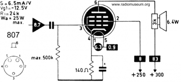
The utterly simple drawing shows the tube pinout, its typical operating voltages and essential static electrical data. I started by clicking on “Pins” in the GUI and entered the electrode names and the two heater connections gleaned from the MTTH drawing.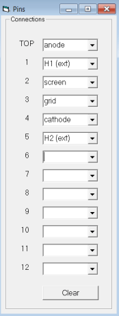 The Pins window has no save option, you just close it by clicking on the red cross. Next I entered some meaningful data on the 807 into the boxes with labels I recognized like Vg start/stop (grid voltage), Vs (screen voltage), Ia (anode current) and Vh (heater voltage). I just played around with having the system draw a graph (“trace”) of the type [I (Va, Vg) with Vs, Vh, constant] selected from the pull-down menu at the top of the window. Note the maximum expected Ia and Is currents of 100 mA and 10 mA respectively I got from MTTH. So yes, in theory it possible to destroy a tube or make it light up red by selecting idiotic values on the uTracer. But then uTracer is your vehicle and you are the driver.
Even if it is hypothetical (and probably flawed at this point, we’ll see…) the configuration I have set up for my 807 can be saved locally for use later using the .uts file format like so:

If you want to “cloud” your uts file for others to use or enhance, go ahead!
These are the settings I saved: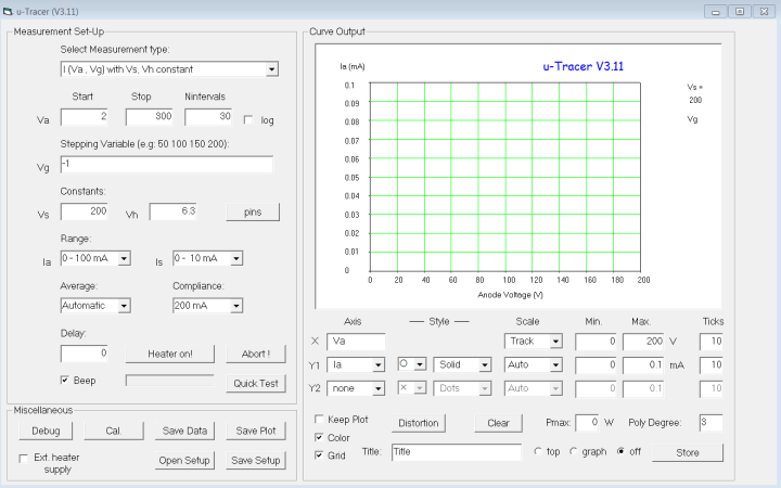
To be continued in week 24.
The moment of truth had arrived as far as dry swimming with the GUI is concerned: launching uTracer 3.11 through the Windows Start button. A typical VB look & feel screen pops up:
Happy to have come this far and learned a few things I was not in the least hesitant about entering some data and “see what happens”. Do remember though that the uTracer hardware is not connected at this point, in fact it’s not even completed and operational. But what can possibly go wrong by entering some tube data into the option boxes on the screen? Right, nothing. So I dug out one of my favorite tubes, the 807.
And then a reliable source of tube data like the 1962 edition of the Muiderkring Tube and Transistor HandBook (MTTH; also recommended by Ronald) to find this, just like radiomuseum.org did before me.The utterly simple drawing shows the tube pinout, its typical operating voltages and essential static electrical data. I started by clicking on “Pins” in the GUI and entered the electrode names and the two heater connections gleaned from the MTTH drawing.
Even if it is hypothetical (and probably flawed at this point, we’ll see…) the configuration I have set up for my 807 can be saved locally for use later using the .uts file format like so:
If you want to “cloud” your uts file for others to use or enhance, go ahead!
These are the settings I saved:
Conclusion
My dealings so far with the software component of the uTracer have strengthened my faith in getting the system to work and help me sort through the enormous pile of tubes waiting to be “traced”. For sure, those tubes will be on their way to Aachen along with the uTracer and my PC.To be continued in week 24.
Read full article
Hide full article
Discussion (3 comments)