
Free New Article: TMC2160 Motor Driver Board
on
Commonly used stepper motor driver types
Stepstick drivers
If you are into hobby projects involving stepper motors or if you are building 3D printers, you are probably familiar with stepstick drivers. They consist of a small PCB with a stepper motor driver IC and pinheader connectors allowing the module to be plugged into a larger board.
 Stepsticks come in many flavours allowing you to choose from a range of driver ICs from several semiconductor manufacturers. Some of the better stepsticks are the so-called SilentStepSticks built around Trinamic stepper driver ICs of which the TMC2100 and TMC2130 are the most popular ones.
These SilentStepSticks are a good choice for 3D printing applications, especially during lenghty print jobs. When using less advanced drivers, stepper motor noise may become objectionable soon. SilentStepSticks not only allow the printer to run silently but also help to achieve better, smoother and more consistent print results.
Besides the standard Enable, Step and Dir signals used to control the motor position, speed and direction, the TMC2130 and TMC5160 based stepsticks also have an SPI interface that allows tuning and configuring several driver parameters. Modern 3D printing software like Marlin supports these drivers and can even autotune the motor drivers via the SPI interface during printing for best results.
While stepsticks are small and easily swappable, they also have a number of disadvantages. Due to their very small size, most use driver ICs with integrated MOSFET bridges that tend to overheat on small boards with almost no copper planes, even with a heatsink mounted on top. This is mainly a problem in more demanding applications like CNC.
Furthermore, stepsticks don’t offer electrical isolation between the motor power supply and the control signals, making them less suitable for complex motion control systems.
Industrial stepper motor drivers
Industrial drivers are commonly used for a broad range of applications and come mostly in an enclosure with terminal blocks for connecting power, the motor leads and control signals. Often, the enclosure doubles as a heatsink for the electronics inside. Some driver enclosures are even suited for direct mounting on the back of a stepper motor. The configuration of the main driver parameters like microstepping and motor current is usually done using DIP switches. More advanced drivers also provide a serial port or a USB interface for configuring and tuning the motor parameters.
Industrial drivers tend to have optocoupler inputs, providing electrical isolation for the control signals (Enable, Step, and Dir signals). Some drivers use ModBus (or even CAN bus) instead to control motor position, speed and direction.
Broadly speaking two driver types are available: open loop and closed loop. The latter use rotary encoders for motor shaft position feedback to the driver. This results in higher accuracy and compensation if the motor skips steps under certain load conditions.
If you need to drive multiple stepper motors, multiple-axis motor drivers are also an option.
The Trinamic TMC2160 motor driver IC
Our 'Wolverine' CNC gantry robot (published in part 1 and part 2) is based on a CNC310 controller board from Eding CNC. As the CNC310 board needs external stepper motor drivers, we considered using drivers based on Trinamic ICs. These would allow the CNC gantry robot to run silently, which is especially important when the machine is used as a pick & place machine for SMT components.
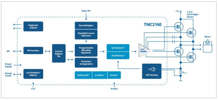
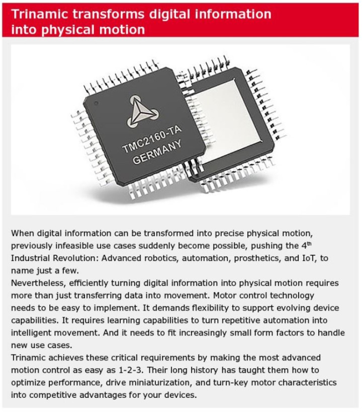
Initially we ran some quick tests with TMC2100 and TMC2130 SilentStepSticks but these were not up for the task and overheated quickly. Instead we looked at the brand new TMC2160 which uses external MOSFETs and was designed for more power-hungry applications (Figure 1).
A TMC2160 breakout board was available but unfortunately configuring the motor driver parameters was possible via SPI only, something the CNC310 board doesn’t support. Also, galvanic isolation between the control signals and the motor power supply was non-existent.
In the end we designed our own TMC2160-based driver with the IC running in standalone mode, and with optocoupler inputs for the control signals. This allows the motor driver parameters to be set using DIP switches.
Most modern stepper motor drivers like the TMC2160 are so-called chopper drivers, which rapidly switch on and off a relatively high voltage (typical eight times the rated motor voltage for best results) to the motor windings. This technique allows controlling the average current per phase. Most chopper drivers use a chopping frequency in the 20–50 kHz ballpark. Since the chopping frequency is above the audible range, noise levels are kept low. With a constant fixed chopping frequency, the average output current is controlled by varying the pulse width of the output pulses, a technique known as pulsewidth modulation (PWM).
Besides the classic constant off-time chopper, the TMC2160 also features two sophisticated SpreadCycle and StealthChop2 chopper modes, which ensure noiseless operation combined with maximum efficiency and best motor torque.
StealthChop2 is a voltage chopper-based principle. It especially guarantees that the motor is quiet in standstill and in slow motion, except for noise generated by ball bearings. Unlike other voltage-mode choppers, stealthChop2 does not require any configuration. It automatically learns the best settings during the first motion after power up and further optimizes the settings in subsequent movements. An initial homing sequence is enough for learning. StealthChop2 allows high motor dynamics, by reacting at once to a change of motor velocity.
SpreadCycle is an advanced cycle-by-cycle chopper mode. It offers smooth operation and good resonance damping over a wide range of speed and load. The SpreadCycle chopper scheme automatically integrates and tunes fast decay cycles to guarantee smooth zero crossing performance and allows for high dynamics and highest peak velocity at low vibration.
Other advances of the TMC2160 include MicroPlyer step interpolation, resonance damping for mid-range resonances, DcStep load-dependent speed control, StallGuard high-precision sensor-less motor load detection and CoolStep current control for energy savings up to 75%. For more information, please refer to the TMC2160 product page and data sheet.
About the circuit diagram
See Figure 2.
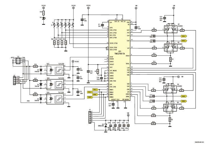
and six DIP switches. This schematic is downloadable at the end of the article.
Our TMC2160 stepper motor driver board is largely based on the Trinamic TMC2160 breakout board. While most of the connections to the TMC2160 are identical and we used the same parts to build the H-bridges, there are quite a few differences.
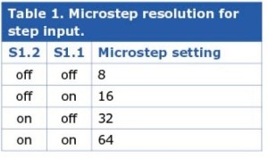
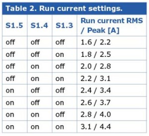
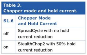
To allow the TMC2160 to operate in standalone mode, we tied pin 22 (SPI Mode) to Ground. As a result, pins 13–16 and 23–25 now become configuration inputs CFG0-CFG6 which we connected to a 6-way DIP switch, S1 (see Tables 1, 2 & 3). Since CFG4 and CFG5 have internal pulldown resistors, we decided to connect external pulldown resistors to the other configuration pins CFG0-CFG3 as well. CFG5 and CFG6 are both connected to S1.6 since driving them to a different level would result in CFG6 drawing a significant current of 20 mA. This would cause the internal linear voltage regulators of the TMC2160 to produce excessive heat.
Type TLP2745 high-speed optocouplers with digital outputs (OK1-OK3) provide galvanic isolation between the control inputs (Enable, Step and Dir) and the TMC2160 driver IC. The inputs are optimized for 5-volt swings. Higher voltages can also be used if extra resistors are connected in series with the control inputs. Please note that we changed the name of the ‘Step’ signal to ‘Pul’ (pulse) to better match the signal names printed on the enclosures of common industrial stepper motor drivers.
An additional 6-pin boxheader connector K3 allows for easy connections using flatcables to our CNC310 breakout board.
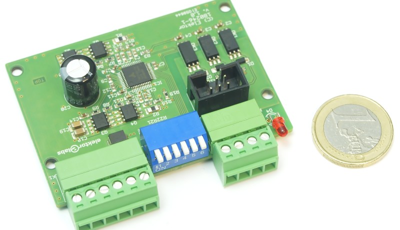
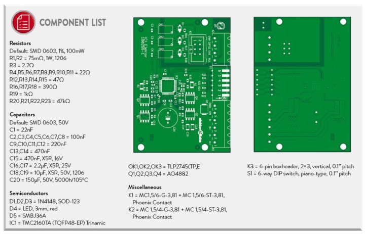
We designed a 4-layer PCB with large copper planes for better cooling performance and used a form factor similar to common industrial stepper motor drivers including Phoenix Contact's "pluggable" terminal blocks, a piano-style DIP switch block and a power indicator LED.
Finally, a type SMBJ36A TVS diode was added to protect the circuit from voltage surges on the supply voltage rails. When the driver is connected to a supply rail through long leads, on power-up the parasitic induction of the leads may cause voltage surges in combination with the MLCC capacitors C18 and C19. Please note that the circuit is not reverse-polarity protected, so be careful when connecting the power supply leads.
We ran some tests with a thermal camera covering various load conditions. With a 24-V power supply, the temperature of the TMC2160 and the MOSFET transistors reached 50 °C and 41 °C respectively, while driving a NEMA 17 stepper motor at various speeds. The motor current was set to 1.6 A RMS using the SpreadCycle chopper (Figure 3).
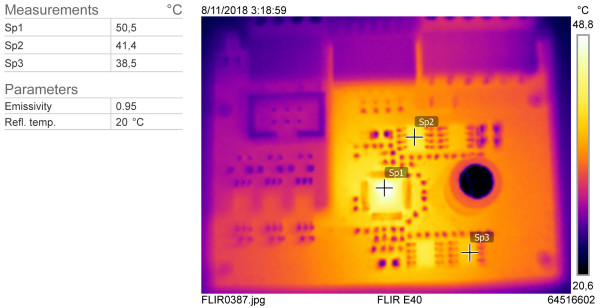
stepper motor with a current of 1.6 A RMS in SpreadCycle chopper mode.
The stepper motor was then replaced with a NEMA 34 motor and we cranked up the supply voltage to 32 V. The current was set to 3.1 ARMS and the motor was pulling a 12-kg (26 lb) kettle bell. Then the temperature of the TMC2160 and MOSFETs rose to 80 °C and 78 °C respectively (Figure 4).
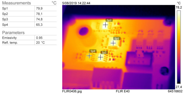
the temperature rose to around 80 °C.
When driving larger stepper motors like NEMA 23 and NEMA 34 types, we recommend sticking a heatsink to the bottom of the PCB or to use a small fan for forced air cooling.
Want more great Elektor content like this?
--> Take out an Elektor membership today and never miss an article, project, or tutorial.
Discussion (1 comment)