
Review: Fortebit Polaris 3G Kit+
A peek under the hood
The build quality, finish and appearance of the GPS tracker is one thing but the unit’s functionality and usefulness depend largely on what’s going on inside. Unscrewing four screws releases the housing cover.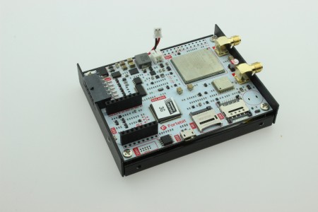
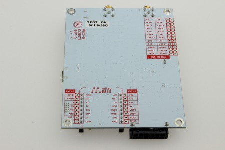
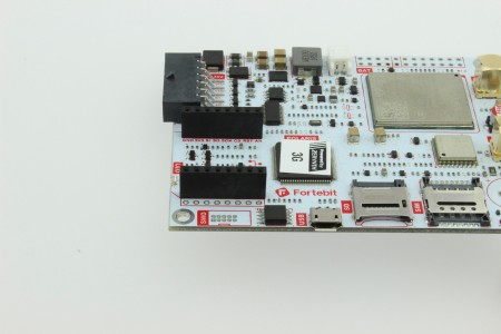
The GPS tracker circuit board has labeling to identify the main mounted components and signals. A Quectel UG96 (3G modem) is used for communication with the outside world and a Quectel GNSS L76 module provides simultaneous GPS, GLONASS, BeiDou, Galileo and QZSS open service L1 reception capability for acquisition of positional information. At the heart of the board’s data processing is an STM32L452VE MCU. This is an ARM Cortex-M4 based chip optimized for low-power modes and provides the user with 512 kB of Flash memory to store application firmware. 10 of the MCU’s GPIOs connect to the outside world via the 12-way main connector. A CAN bus interface is also provided for communication with a vehicle or other systems. Internally the board is also fitted with a mikroBUS slot and a 24-way expansion header strip (unmounted). The GPS tracker offers many ways to add to the existing hardware and interface with the signals as necessary.
Stashed away under the PCB in the Polaris 3G kit + is a 2500 mAh LiPo battery which allows the unit to operate in stand-alone mode without an external supply. As supplied, the battery lead is not plugged into its connector on the board edge. This ensures the battery has not been discharged during storage and also complies with the regulations applying to the transportation of battery-powered equipment. There is no indication on the packaging that a battery is included in the kit.

A micro-USB socket along the board edge is used to upload new software to the GPS tracker and also to output data to an external system. This port is wired directly to the processor and uses its in-built USB controller. A useful feature on the board is its 10-way SWD debug connector for the STM32 which you will not find on many other GPS trackers. One curious detail in the Fortebit technical description of the main connector suggests that the inputs and outputs are fully isolated and can withstand 250 V at 5A? A glance at the circuit diagram shows no galvanic isolation circuitry on the tracker that could withstand such abuse. Then you realize they have just listed the connector specification from Molex… nothing to do with the signals it is actually handling in the tracker circuit. Please don’t be tempted to connect any signal greater than standard low-voltage logic levels as described under the ‘Electrical Characteristics’ heading in the Polaris manual. The hardware is also designed as open source so you can add to it and configure it according to your own needs just as you can the software.
Read full article
Hide full article
Discussion (0 comments)