
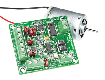
Precision Control for DC Motors
Get the right spin every time!
Continue reading this article with an Elektor Membership.
Join tens of thousands of engineers and electronics enthusiasts worldwide as a
member. Enjoy access to Elektor Magazine, the Elektor library, exclusive discounts,
early notification about Academy Pro products, and more. Select a membership
today and start exploring everything Elektor has to offer. Log in here if you are already a member.
PRINT (Gold)
- 8x Elektor Magazine (Print)
- 8x Elektor Magazine (Digital)
- Access to the Elektor Archive*
- Access to over 5,000 Gerber files
- 10% at the Elektor Store*
plus a delivery charge of 20 euros (US, UK, Ireland).
*Member discount and unlimited archive access only for full GOLD or GREEN members. Trial members have limited access to the online archive.
DIGITAL (Green)
- 8x Elektor Magazine (Print)
- 8x Elektor Magazine (Digital)
- Access to the Elektor Archive*
- Access to over 5,000 Gerber files
- 10% at the Elektor Store*
* Member discount and unlimited archive access only for full GOLD or GREEN members. Trial members have limited access to the online archive.

BUY THIS ARTICLE (PDF)
Extra info / Update
* Supply voltage: 12 V
* Maximum output current: 2 A
* Minimum supply current: 11.2 mA
* PWM range: 0 – 100 %
* External control voltage:
0.16 V (PWM 0 %, 0/5 V range)
4.88 V (PWM 100 %, 0/5 V range)
0.27 V (PWM 0 %, 0/10 V range)
9.7 V (PWM 100 %, 0/10 V range)
* Input impedance (Pin 2 of K2):
6.43 kOhm (0/5 V range)
15.36 kOhm (0/10 V range)
Components
The BOM (Bill of Materials) is the technically exhaustive listing of parts and other hardware items used to produce the working and tested prototype of any Elektor Labs project. The BOM file contains deeper information than the Component List published for the same project in Elektor Magazine. If required the BOM gets updated directly by our lab engineers. As a reader, you can download the list here.
Want to learn more about our BOM list? Read the BOM list article for extra information.
Build This Project
Bring this design to life with the Elektor PCB Service, powered by Eurocircuits. Upload the project files and order professionally manufactured PCBs or assembled boards through a proven European production platform.
Supporting KiCad, Eagle, Gerber, and ODB++ formats, the service is suitable for everything from prototypes and validation builds to series production and volume manufacturing.
Made in Europe. Fast. Reliable. Professional.
Bill of Materials
Resistors
All SMD 0805, 150V, 5%, 0.1W)
R1 = 2.7k?
R2 = 8.2k?
R3,R4 = 11k?
R5 = 5.6k?
R6 = 2.00k?
R7 = 330?
R8 = 4.7k?
R9 to R14 = 10k?
R15 = 2.2k?
P1 = 5k SMD preset, Bourns 3314G-502E
Capacitors
C1 = 10nF 50V, X7R, SMD 0805
C2,C4,C6,C7,C8 = 100nF 50V, X7R, SMD 0805
C3 = 10µF, 16V, X5R, SMD 0805
C5 = 47µF, 6.3V, 0.5?, tantalum, SMD case B
C9,C10 = 220µF, 16V, 0.1?, tantalum, SMD case
Semiconductors
D1,D2 = TS4148RY, SMD 0805 (Taiwan Semiconductor)
LED1 = LED, green
IC1 = SG3524D, SMD SOIC-16 (Texas Instruments)
IC2 = MC74HC4053ADTG, SMD TSSOP-16 (ON Semiconductor)
IC3 = AD5301BRMZ, SMD MSOP-8, only with I2C populating (Analog Devices)
IC4 = BD6222FP-E2, SMD HSOP-25 (ROHM)
Miscellaneous
K1A,K1B,K2 = 3-way PCB screw terminal block, 5mm pitch
K3,K4 = 2-way PCB screw terminal block, 5mm pitch
JP1,JP5,P6,JP7 = 3-pin pinheader, vertical, 0.1’’ pitch
JP3,JP4 = 2-pin pinheader, vertical, 0.1’’ pitch
JP1,JP3–JP7 = jumper, 0.1’’ pitch
PCB # 140562-1 from Elektor Store
We buy at:

Discussion (0 comments)