
±40-V Linear Voltage Regulator: An Alternative Power Supply
on
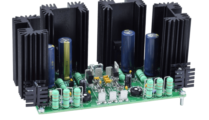
For those who frown upon any shape or form of switched-mode power supply (SMPS) for the high-end Fortissimo-100 Power Amplifier, this project yields a 500+ VA, linear, symmetrical voltage regulator marked by low dropout voltage, high output current, and excellent stability — all obtained from discrete components and built from a kit!
Bearing in mind that nearly all high-performance audio power amplifiers benefit from a stabilized supply voltage, this linear power supply is specifically designed for a symmetrical output voltage of ±40 V and peak currents of 13 A (15 A peak achievable). As an example, the average current drawn by a Fortissmo-100 amp driving a 3 Ω load is roughly 4 A per regulator.
Design Considerations
The Elektor Fortissimo-100 high-end audio power amplifier was proven to work best with a regulated ±40 V power supply, ruling out a “bare-bones” supply consisting of a transformer, a (bridge) rectifier, and a set of thick reservoir capacitors. A switched-mode power supply may not quite fit the bill either but this is more a matter of personal taste as the SMPS800RE does a good job. Still, there may be compelling reasons to favor a linear regulator built from through-hole components only, like the amplifier itself.
For the voltage regulator to work without dropouts (output voltage dips), the input voltage of the circuit must exceed the output voltage by at least 3 V higher, or even more in case of mains voltage fluctuations. Compared to most SMPSes (with a wide AC voltage input range), a linear regulator is less efficient and a large power transformer is called for with a higher power rating than without the linear regulator.
Today, most off-the-shelf power (“mains”) transformers are marked by standardized secondary voltages. To create ±40 VDC directly, a transformer rated at 2× 30 V is the most likely choice. The resulting no-load DC voltage is usually around 42 VDC, largely depending on internal regulation of the transformer and voltage drop across the rectifier diodes. In practice, the no-load output voltage of a power transformer is always a few percent higher than loaded. The next higher standard secondary voltage is 35 V, which results in approximately 49 to 50 VDC or more at low output power — close to 52 V was measured in a Labs test setup.
With an 8 Ω load on the power amplifier, the regulator requires a small smoothing capacitance only. The advantage of the larger ripple voltage is a somewhat lower power loss in the supply regulator(s). But, at lower impedances, the ripple should not go beyond the dropout voltage (43 V at 10 A). In a lab test, a 2× 35 V, 300 VA toroid (ring core) transformer with 20,000 µF worth of smoothing capacitance appeared sturdy enough to feed the regulator. The maximum (near-clipping) sine wave power at 20 Hz and 0.1% THD+N into a 3 Ω load caused a mere 1.8 Vpeak of dropout at the supply output. Mind you, the continuous output power then is 227 watts into the 3-ohm load and the 300 VA transformer is slightly overloaded. This, however, was not enough to trip the Fortissimo-100’s protection.
Theory of Operation
The basis of any voltage regulator is measuring the output voltage, comparing it to a reference level, and controlling the output stage accordingly to counteract any changes. Although the present regulator circuit follows that concept, one dissimilarity that is marked is its much higher secondary reference voltage, which, at a little over 33 V, is relatively close to the 40 V target output voltage. The higher the reference voltage — 33.6 V here — the more gain left to a (simple) circuit to increase both the ripple rejection of the input voltage and the output voltage regulation.
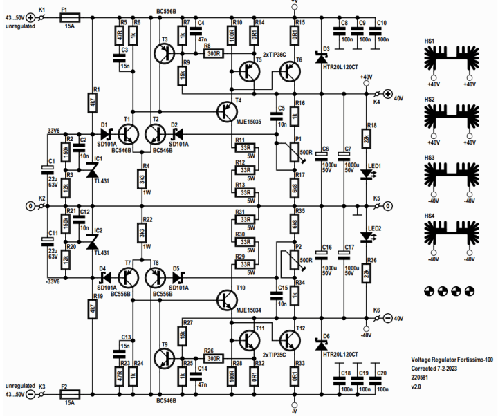
Simply put, the circuit consists of a reference voltage, a differential amplifier, and an output buffer. Additionally, a safe operating area (SOA) protection is added to both regulators. Let’s look at Figure 1 to explore the operation of the positive regulator.
Reference Voltage
The reference voltage is not created by a Zener diode, as standard Zeners typically have considerable temperature coefficients. Special temperature-compensated versions are hard to come by these days, especially 33 V versions. Instead of a Zener diode, a type TL431 adjustable-precision shunt voltage reference is used with a maximum working voltage of 36 V. Its internal reference voltage (i.e., the primary reference voltage of the 40 V regulator) is typically 2.495 V. The cathode current through the TL431 is set by resistor R1. If the input voltage is between 43 and 50 V, the current is set between 1.9 and 3.4 mA, which turned out to be adequate for a stable 33.9 V reference voltage to be created. The 33.9 V is set by resistors R2 and R3, as follows:
VKA = 2.495 × (1 + R2 / R3) + IREF × R2
The TL431’s adjust current, IREF, is typically 1.8 µA, so the reference voltage is theoretically 33.95 V. However, this is specified at a cathode current of 10 mA, while in the prototype this current is lower and so is the voltage: 33.55 V was measured in practice. The TL431 is decoupled by C1 while C2 improves the overall stability.
Differential Amplifier
The differential amplifier is minimalistic, consisting of T1 and T2 with R4 as a current source. The voltage at the base of T1 is fairly constant. Ditto for the voltage across R3, even with the slightly varying voltage — with temperature — across the base-emitter junction of T1 and across D1. Schottky diodes D1 and D2 limit a (just conceivable) reverse voltage of T1 and T2’s base-emitter voltages.
To reduce the influence of the voltage drop across each diode, while not affecting the input offset voltage of the differential pair too much due to changes in temperature, the pair is positioned next to each other on the PCB so both diode junctions are at the same temperature. A few millivolts — or even tens of millivolts — offset also caused by differences between T1 and T2 have no real effect on the much higher 40 V output voltage. Even an offset change of 30 mV means under 1% variance in the output voltage, which is inconsequential to the operation of the power amplifier.
The voltage across collector resistor R6 is used to drive the output stage. R5 and C3, as well as C4 and C5, form the frequency compensation to keep the regulator stable, even with SOA (safe operating area) protection T3/R7/R8/R9 active. Potential divider R16-P1-R17 measures the output voltage and presents the negative feedback for the differential amplifier. To compensate all tolerances, P1’s output voltage range is approximately 38.6 V to 41.1 V. With the trim pot wiper at mid-travel, the output voltage will be pretty close to 40 V.
Output Stage
Although there are transistors that can handle the maximum output current called for when a constant 50 V input voltage is applied to the regulator, two transistors, T5/T6, are chosen to:
- limit the power dissipation per device to safe levels;
- increase the overload range;
- achieve lower dropout voltage and greater safe operating area.
Implementing these criteria reduces the risk of damage to the output stage in case there’s an overload condition or even a short circuit. The larger PNP power transistors are type TIP36C (cf. the NPN TIP35C in the negative regulator) and are easily available from several manufacturers. PNP transistors are used in the positive regulator to keep the minimum voltage drop of the output stage as low as possible, the base currents flowing toward ground.
The dropout voltage is the sum of the transistors’ saturation voltage and the voltage drop across the emitter resistors. A lower value for the emitter resistors would reduce the dropout voltage a little, but the currents through the two transistors can divert too much. At high collector currents, the transistors’ gain is very low, and an additional transistor (T4) is needed to buffer the output of the differential stage. To prevent the saturation voltage of T4 increasing the dropout voltage of the output stage, its collector is connected to ground through a series connection of resistors. This limits T4’s power dissipation as well as its heatsink requirement. However, there’s a catch in doing this: Should — by whatever cause — the input voltage fall below the dropout voltage, T4 will conduct permanently and the dissipation in its collector resistor will be quite high at 16 watts at 100 Ω total resistance and 40 V input voltage applied. This should never occur, though, hence three 5-W resistors are used to prevent a burnout of this collector resistor.
An additional advantage of this collector resistor is its limiting of T5 and T6’s base currents and thus acting as a simple current limit. The real protection, though, is formed by T3. The output current is measured by voltage divider R7/R8 as the voltage drop across the emitter resistor of T5, and this drives the base of T3. When, for instance, the current through R14 is about 7 A, the total output current is 14 A. The highest expected output current is a little over 12 Apeak with a 3 Ω load on the amplifier output. T3 will start conducting, and — due to R9 — even sooner, depending on the voltage across T5. The exact level at which T3 is forward-biased is temperature-dependent and will be lower as temperature rises — an additional protection, and, with music, this won’t be an issue.
D3 protects the output stage in case the input voltage is suddenly disconnected or short-circuited. T5 and T6 are decoupled with a pair of 1000 µF, low-ESR capacitors. LED1 indicates the presence of the +40 V output voltage.
Although from the photos it appears that D6 is reverse-fitted on the PCB, in fact, both D6 and D3 can be fitted either way around and still function correctly. The HTR20L120CT diode in its 3-lead TO220 case has two internal diodes with a common cathode connected to the device’s center lead.
The regulator input is protected by a 15 A fuse. The maximum RMS (root-mean-square) current must be considered, and at maximum half-wave sine current, the RMS value is Ipeak/2, i.e., 6.5 A. However, at very low frequencies like 16.4 Hz (if you like organ music), the peak current may last several milliseconds. To make sure the fuse doesn’t blow under such conditions, a 15 A type is used here, which, as a bonus, also reduces the voltage drop. If much more power is taken by the amplifier and/or the regulator, the primary fuse linked to the power transformer blows. The 15 A fuse will reliably blow should there be a sudden short circuit “behind” it.
Kit, Construction Manual, and Bill of Materials
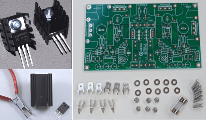
The Elektor Store offers a comprehensive kit for the Linear Voltage Regulator project , containing the printed circuit board (PCB) and all parts listed in the bill of materials (BoM, or component list). This superb kit hopefully defeats readers’ efforts in purchasing parts (electronic and mechanical) and having PCBs made to order.
Along with the kit comes a 12-page Construction Manual giving step-by-step instructions on assembling the project and hopefully reaching a perfect result. The manual is rich in drawings and photographs, a few of which are shown in Figure 2. It also contains many tips and details on precise soldering, part positioning, tool handling, and simple mechanical work required to complete the project’s build.
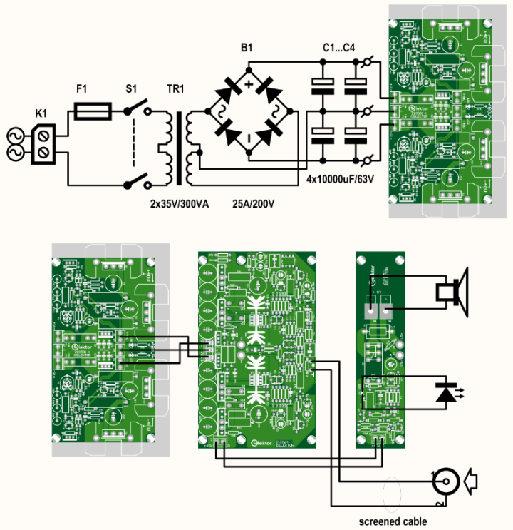
Since the proposed regulator isn’t a complete power supply without the usual circuitry of a power transformer, a rectifier, and smoothing capacitors added, a suggested schematic — tuned to the Fortissimo-100 amp — is given in Figure 3. The parts for this section are not included in the ±40 V Linear Voltage Regulator kit and must be purchased locally.
linear voltage regulator / Fortissimo-100 combo (bottom).
Safety Consideration
Although the construction of the project and its practical use are detailed in the Construction Manual, we feel obliged to print the following safety notice in this article as well: The large heatsinks are connected to the ±40 V output voltage, not to GND. Always remove the input voltage before touching or working on the regulator!
Results Achieved
At Elektor Labs, a test setup was built to verify the operation of the Fortissimo-100 amplifier in combination with the ±40 V Linear Voltage Regulator described here. Both units were built from their respective Elektor kits. The following key ingredients went into the unregulated supply section:
- 1 pc. TX-146-300-235 power transformer (300 VA, 2× 35 VAC secondary).
- 2 pcs. 10,000 µF electrolytic capacitor per supply voltage rail (i.e., 20 mF on each rail).
- 1 pc. SB352SBPC-style bridge rectifier, 35 A/200 V (25 A/100 V satisfactory).
into 8 Ω and powered by ±40 V Linear voltage regulator board no. 220581-1.
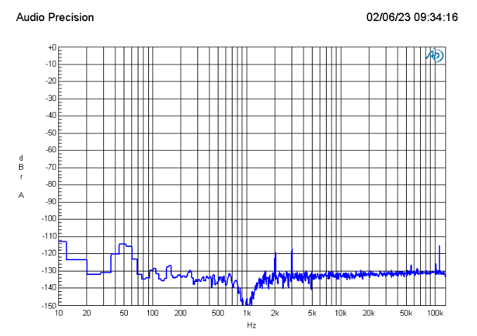
At low output levels from the Fortissimo-100, the frequency spectrum shows that very small improvements can be achieved when compared with the SMPS800RE switched-mode power supply (Figure 4). The graph shows the frequency spectrum at 1 W into 8 Ω. The SMPS800RE’s switching artifacts are gone, but the rest of the spectrum is essentially the same. The overall performance of the combo is impressive, with harmonic distortion plus noise as low as:
- 0.0007% (1 kHz, 1 W, 8 Ω, B = 22 kHz)
- 0.0013% (1 kHz, 1 W, 8 Ω, B = 80 kHz)
The ±40 V linear voltage regulator described here and available as a kit from Elektor is a good alternative to the best, yet affordable, switch-mode power supplies on the market today, and should satisfy those of you objecting, however lightly, to the concept or performance of “them @#!%^ switchers”. Feel free to join the technical discussions on the ±40 V linear voltage regulator on the Elektor Labs page created for the project.
Editor's note: This article (220581-01) is scheduled to appear in Elektor September/October 2023.
Questions or Comments?
If you have any technical questions, you can contact the Elektor editorial team by email at editor@elektor.com.
Discussion (0 comments)