
Breakout Board for a 5-A DC Motor Driver
on
Today's makers and students are often in a hurry and lack the skills to design and solder electronic circuits. They are more into “shields,” and handling a soldering iron is a challenge. So, I’ve developed a breakout board for the Monolithic Power Systems MP6619 motor driver, which can be used well for one’s own motor-based projects.
This article is a journey of discovery to an MP6619 breakout board (BoB). This chip is a new compact H-bridge for controlling low-cost brushed DC electric motors and solenoids. These DC motors are the most accessible and affordable for hobbyists involved in building small robots, model making, and creative projects. This is a story about the educational journey I had to go through to develop and test this breakout board.
The Motor Driver Adventure Begins
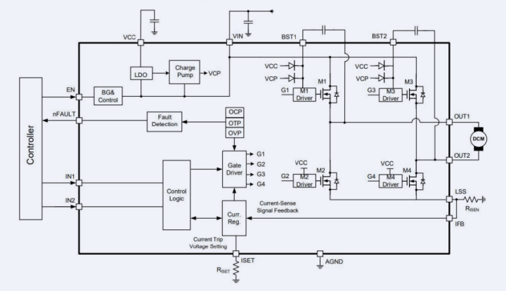
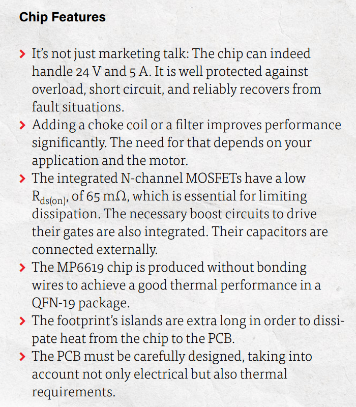
One day, I received an email from a component distributor about a brand-new H-bridge component: the MP6619 motor driver. Figure 1 shows its internal block diagram. This tiny “miracle” of just 3×3 mm with impressive specifications such as 24 V and 5 A, and other aspects, caught my attention (see the "Chip Features" frame). How can this be possible? So much current, no heatsink, and all protection features in such a miniature package? This must be marketing talk, I thought. The alternatives are easily 10 times larger.
But, my curiosity was piqued, and I wanted to know if this was true and whether it would be useful for my projects. So, I ordered a few. After just two days, they were on my desk: Wow, they were tiny! Only 3×3 mm with 0.2 mm between the contacts and no legs. What have I gotten myself into?
I dive headfirst into this subject. Despite the low price of around €2.50, the small dimensions and unusual footprint of the MP6619 turned out not to be directly applicable to my projects. A BoB was needed that would make the MP6619 more manageable and suitable for testing and integration. But, there was no BoB available for this tiny Quad, Flat, No-lead, 19-contact (QFN-19) footprint. So, I had to develop such a board myself. My adventure with the MP6619 H-bridge began!
Designed with KiCad
To develop an MP6619 breakout board, I started by studying the datasheet and drawing the BoB schematic in KiCad. First, I drew the symbol and footprint (these were not available in the library or SnapEDA), and then the layout.
I paid extra attention to the placement of the R(i-sense) shunt resistor and the connection of power pads. This shunt resistor is used to measure the MOSFET drivers’ current. This is crucial for the proper functioning of the breakout board. Voltage drop across the traces should be considered, too, during the PCB layout process.
The OCP (Over-Current Protection) is adjustable with an external resistor. Without that, the chip switches off when the voltage across the shunt resistor reaches 200 mV. The datasheet suggests a shunt of 0.04 Ω, which limits the maximum current to 5 A (V = I × R). By adding an R(i-set) of 80 kΩ, the limit is set to 100 mV, allowing you to reduce the current limit when using the same shunt resistor. Other resistor values are also possible. I chose a shunt of 0.05 Ω for my first test because I had it in my drawer. This results in an output current limit of 4 A.
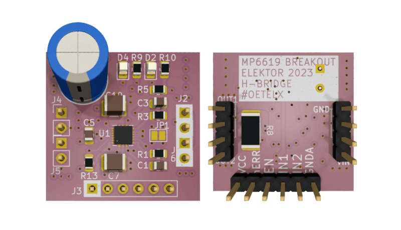
I quickly made the first version of the BoB PCB layout without in-depth study, as I wanted to start testing soon, but I rejoiced too soon. The first BoB included two MP6619 chips, LEDs, resistors, capacitors, and connectors. At that time, I still thought PCB terminal blocks would be useful. Four copper layers were needed, I placed many vias, a ground plane, and used the widest possible traces due to the high currents. That was a day’s work. A week after sending the data to a Chinese manufacturer, I had the boards on my workbench. Soldering the QFN was the greatest challenge, as the chips were smaller than anything I was used to.
To get the QFN in place with all connections correct, a stereo microscope, a good temperature-controlled soldering iron, a hot-air soldering iron, plenty of flux, and even more patience were required. Once the QFN was in place and the sweat wiped from the forehead, those other “normal” SMD components were child’s play; they seemed gigantic compared to the QFN. The solder island for the PCB terminal block is larger than the entire QFN chip (Figure 2)! I posted this first version on the Elektor Labs website.
First Tests
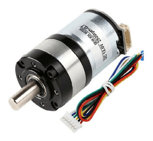
The first tests were done with a small DC motor that was on my workbench. It was a simple 12 V model with a stall current of under 5 A (Figure 3). The MP6619 internally consists of two half-bridges, with each half-bridge having one input (IN1, IN2). The chip itself ensures the correct timing of the high-side and low-side MOSFETs so that no short-circuit between the power rails occurs. The chip is protected against all typical problems. Its integrated UVLO (under voltage lockout), OVP (overvoltage protection), OCP (overcurrent protection), and OTP (over temperature protection) should safely handle nearly all error situations, which we’ll see!
Connecting IN1, IN2, and EN
The inputs are equipped with pull-down resistors. As soon as the EN input receives a High level, the chip is activated, and the internal voltage regulator starts operating. At that moment, the MP6619’s VCC output provides a voltage of 5 V. I used a small 100 nF decoupling capacitor to stabilize this voltage. If the 5 V is up, the N-channel MOSFETs also become active. Depending on the input levels at IN1 and IN2, either the high-side or low-side MOSFETs are switched.
It is safe to have 3.3 V to 5 V logic levels at the inputs. So it is no problem to connect the BoB to an ESP32 or an Arduino. For my initial tests, I used switches to apply 3.3 V to the inputs, and connected the motor to the BoB’s outputs.
Partial Success
My motor didn’t want to spin, the nFault output immediately went low (error indication LED turned on), but I didn’t have a short circuit at the output. Significantly reducing the input voltage eventually allowed me to slowly rotate the motor counterclockwise and clockwise. It’s important to note that I didn’t provide any PWM speed control yet.
I experimented with decreasing the shunt resistance and increasing the Rset resistor to get the motor moving, which ultimately resulted in a “human error” — 12 V on IN1, a burnt BoB as result, and a deep sigh of frustration. The PCB went up in smoke, and I needed to stuff a new BoB with components.
Another BoB and More Tests
Eventually, I found out that the motor is equipped with noise suppression capacitors connected in parallel to the commutator. As a result, the motor behaves less inductively and more capacitively. This causes the OCP to immediately kick in when there is a current spike to the motor. This “overload” causes a timeout of 1 ms before the MP6619 motor driver tries again. This process repeats again and again, resulting in a soft, squeaking sound from the motor.
Removing these capacitors partially helps to control the motor at somewhat higher voltages. Meanwhile, after studying the datasheet more carefully, I also had improvement plans for my BoB design and decided to create a new version.
New Design and Layout
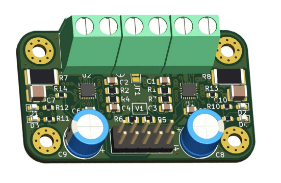
For my second version, the design and the layout had to be adjusted. I made the following changes:
- Only one MP6619 chip.
- The position of the shunt was revised.
- A 0.1″ pin header instead of terminal blocks; no mounting holes.
- A clear silkscreen; only the minimal number of components.
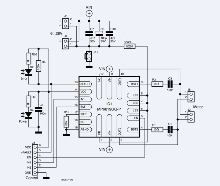
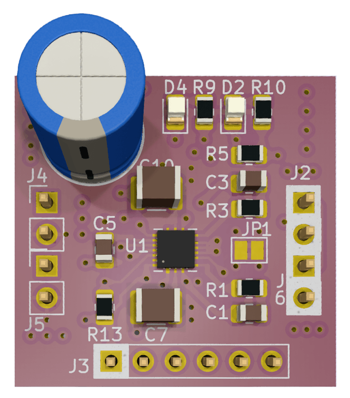
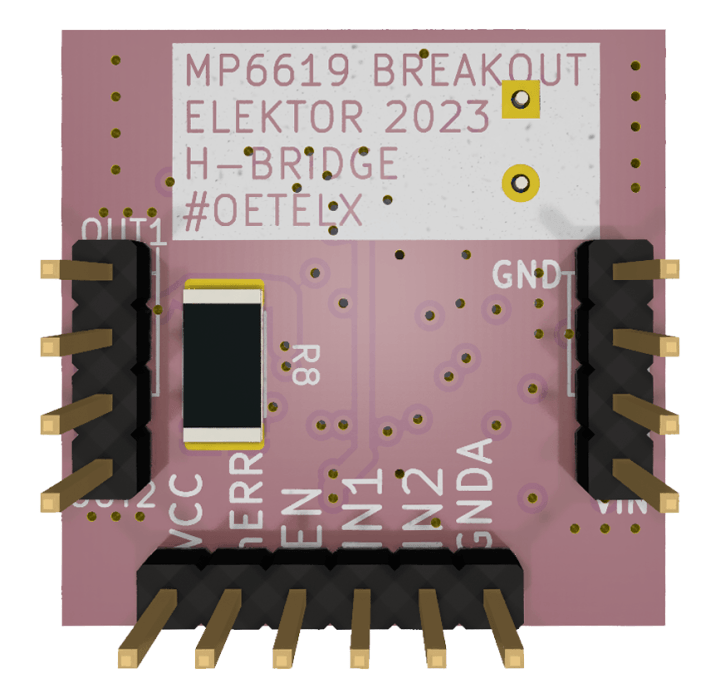
This resulted in a new schematic (Figure 4) and subsequently also a new PCB (Figure 5 and Figure 6) with four layers and an outline of only about one square inch (25×25 mm) produced in a production panel with ENIG finish (electroless nickel immersion gold). After populating the BoB, I got a really compact module, which, I believe, can be controlled by nearly every microcontroller.
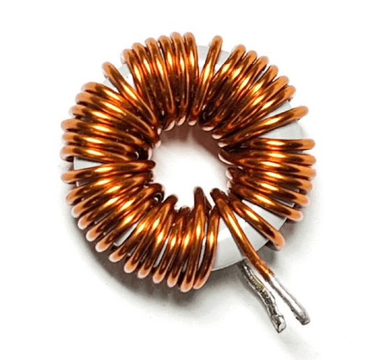
I used the same motor as in the first test. OVP and ULVO behaved well. Now I tried it with PWM control to realize speed control. Testing with frequencies from 1 kHz to 50 kHz yielded the expected behavior: The motor was nicely controllable. The example from the datasheet uses 20 kHz, and that worked fine at low voltages. But, at higher voltages, again the OCP kicked in and the motor stopped. By adding an extra 220 µH inductor (from the workbench, like the one from Figure 7) in series with the motor, the control behavior was significantly improved, and the speed range was increased. As a result, the motor delivered more power, and the OCP kicked in less frequently. With these extra inductors, the solution seems to be suitable for use in projects.
Under some conditions, the motor returns energy, which flows back into the H-bridge. This energy is dumped onto the power rails through the diodes in the MOSFETs, as the motor also functions as a generator (a DC motor’s EMF). In my tests, I used low-ESR electrolytic capacitor C8 in parallel to the power source. With this last improvement, the BoB was stable.
Optocouplers
Figure 8 shows my test circuit. I decided to use optocouplers to provide galvanic isolation between the controlling side and the motor drivers, because the power supply of a motor usually carries considerable noise levels. EMI can also cause problems. The isolation reduces the risk of interference in the low-voltage signals and prevents strong pulses generated by the motor and its driver from reaching the sensitive microprocessor and other electronics.
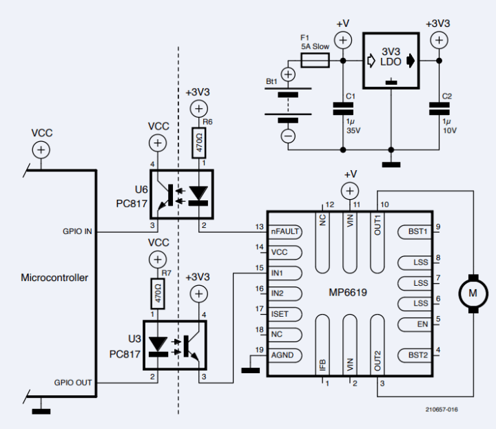
The optocouplers’ input LEDs can be driven directly from a microprocessor pin using a 470 Ω resistor in series. On the output side, the phototransitor’s emitter is connected to the BoB’s IN1, and therefore to the MP6619’s input, and its collector coupled to a logic voltage provided by a 3.3 V LDO voltage regulator powered by the motor’s power supply — in my case, a battery. This is sufficient to ensure reliable and stable operation.
Figure 8 also shows how you can also bring the H-bridge’s nFault signal (Open-Drain output) to the MCU via an optocoupler in the same manner as the other way around. In such a case, the connected microcontroller’s GPIO will need a pull-down resistor.
QFN Packages
The FCQFN packages (Figure 9) can have irregularly shaped pads, often arranged in long, narrow strips. Unlike regular QFN packages, heat is dissipated through many of these pads instead of one large central pad. This poses some challenges for PCB design since there are many pads, all with different signals, that need to be connected with copper areas.
Small vias can be placed within the pad areas (via in PAD). On multilayer PCBs with power and ground planes, vias can directly connect these pads to the planes. In other cases, copper must be directly attached to the pads to dissipate heat from the IC to larger copper areas. A layout guideline is available here.
The greatest obstacle I encountered during this project was soldering the MP6619 chip. To overcome this problem, I experimented with various techniques, and eventually succeeded with lots of flux, leaded solder and hot air, but it remained a challenge to place the chip precisely.
Once in place, the molten solder’s surface tension ensures that the chip is properly aligned with the pads. A lot of practice turned out to be necessary. My conclusion is to purchase a hotplate to simplify the soldering process.
Motor Driver Breakout Board
In this article, I shared my experiences in designing and building a breakout board for the MP6619 H-bridge motor driver. I discussed the importance of using optocouplers to provide electrical isolation, and shared my insights into working with flip chip QFN packages and the challenges involved in soldering small components.
The MP6619 breakout board offers a very compact solution for driving low-cost DC motors with brushes, making it a great choice for hobbyists and makers who are building small robots and other creative projects. All design files and production files are open-source and can be found on my GitHub page. The MP6619 motor driver is widely available in small quantities from distributors such as Farnell, Mouser, and directly from Monolithic Power Systems.
This article (210657-01) appears in the September/October 2023 edition of Elektor Mag.
Discussion (1 comment)