
A Compass Rose Using the GY-271
on
Building an electronic compass from three key parts should be child’s play: a magnetic field sensor on a breakout board, a NeoPixel LED ring as a compass rose, and an Arduino running a ready-made program to manage everything. But when the compass does not work quite as one had imagined it would, there is no choice but to go back to basics to track down a perplexing problem. And the GY-271-based solution to the problem is no less surprising!
The Idea
In the olden days when out for a cycle ride in unknown territory, a map pocket was an indispensable accessory. Nowadays you simply clip a smartphone to your handlebars or, for a larger-scale view, put a tablet in your front basket. On my smartphone, I have the OsmAnd app installed, which uses maps from OpenStreetMap. Unfortunately, the device does not have a compass, and so I have to make do with the tiny course direction indication displayed on the OsmAnd screen; unfortunately, when I stop moving, this indication stops working and so is of little use in trying to orient myself. The map on the screen spins around this way and that, and so I have to move 20 m or so (initially in the wrong direction, natch) so that I can reorient myself properly.
I therefore hit upon the idea of taking with me a separate clearly-visible compass which would not have a delicate needle that could suffer from mechanical vibration. Looking through back issues of Elektor, the idea of an electronic solution began to crystallize: using current-generation electronics it should be possible to make a reliable and accurate device.
An approach using an Arduino Nano, a NeoPixel LED ring, and the GY-271 is described at [1], including a circuit diagram and source code. It appeared to do everything I wanted, so I opened my wallet and bought a module. Since I like to have a few spare parts on hand and the module is inexpensive, I bought three units.
The GY-271 Compass Module
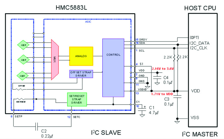
The GY-271 is a breakout board designed for the Arduino, and its header pins fit perfectly into an ordinary breadboard. The main IC on the board is a three-axis compass with part number HMC5883L or QMC5883: this device is often found in smartphones and so is a cheap mass-market product. The internal circuitry of the IC is shown in Figure 1. The support components on the module board are just a 3.3 V LDO voltage regulator, some smoothing and bypass capacitors, and two level-shifters for the I2C bus interface. We can deduce from this that the module can be powered from a 3 V to 5 V supply and that it talks to a connected microcontroller (which could be an Arduino, a Raspberry Pi or some other ‘intelligent’ component) using I2C. The details of the communication protocol are described in great detail in the accompanying documentation and in a free e-book of applications available in several languages.
Because we do not have to deal with any analogue signals, building the circuit is mostly just a simple matter of connecting up the power supplies. The LED ring is powered over two solder pads providing power and ground, and there is a single logic signal required to provide the clock to the NeoPixels. In order to save space, an Arduino Pro Mini was used, and the Arduino IDE needs to be configured correspondingly. An FTDI USB-to-serial cable is required for programming the Arduino.
So Far, Not So Good
In theory, then, building the compass and installing it on my bike should present no difficulties whatsoever. However, the first test soon put paid to that idea! Only one quadrant actually worked, and then the ‘needle’ jumped by 180 degrees. Trawling through the source code (since withdrawn) for the possible cause turned up nothing, and I put the problem down to low-quality no-name products bought on eBay.
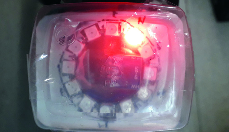
In short, the only pragmatic thing to do was proceed empirically to try to run the problem to ground. From early experiments I determined that the device was highly sensitive to external fields, as found, for example, in the neighbourhood of my laptop. Trying to experiment with a set-up that is a precarious mass of wires is not recommended, and so I constructed a more robust experimental set-up, as shown in Figure 2. To explain a little what can be seen there: an upside-down coffee mug, guaranteed free of magnetic anomalies, was selected. The board and (not visible in this picture) sensor and the ring of LEDs are attached to the base of the mug using elastic bands, with a pen underneath to act as a ‘north’ indicator. A small piece of wood and a sponge act simultaneously as spacer and bearing. The directions of the x- and y-axes are indicated on the component side of the GY-271 module. The red cap of the pen corresponds to the direction of LED 0 and the negative x-direction (!) of the sensor, which is mounted with component side facing down. The z-axis of the sensor is not used in this design, but the device should be adjusted so that it reads as zero to minimize error in the system. (The z-axis reading, in conjunction with a bit of mathematics, might be usable to measure those ‘hors catégorie’ climbs in the mountains.) The mug rests on a sheet of paper on which a rudimentary compass rose has been drawn. A central circle has been cut out so that it can easily be rotated. And, though it might not look particularly sophisticated, this set-up not only generated reproducible results but also led to a remarkable ‘aha!’ moment.

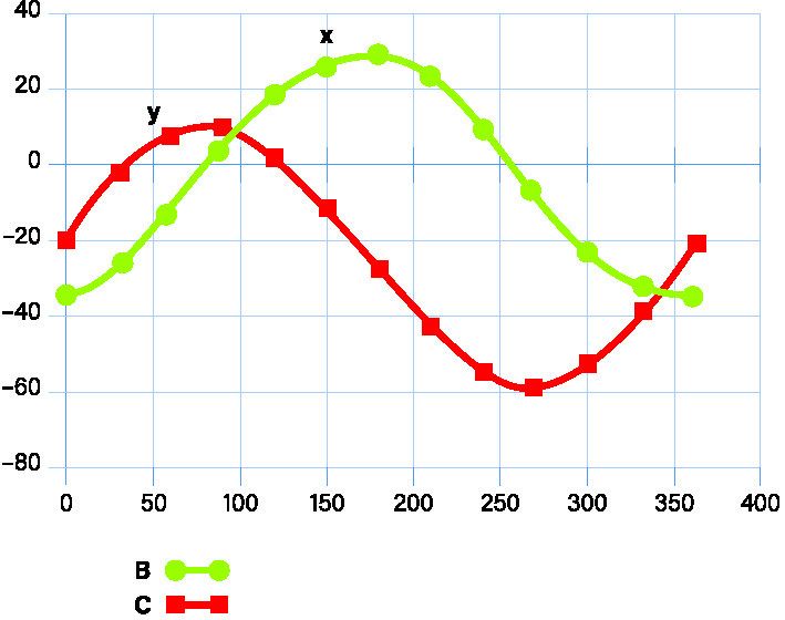
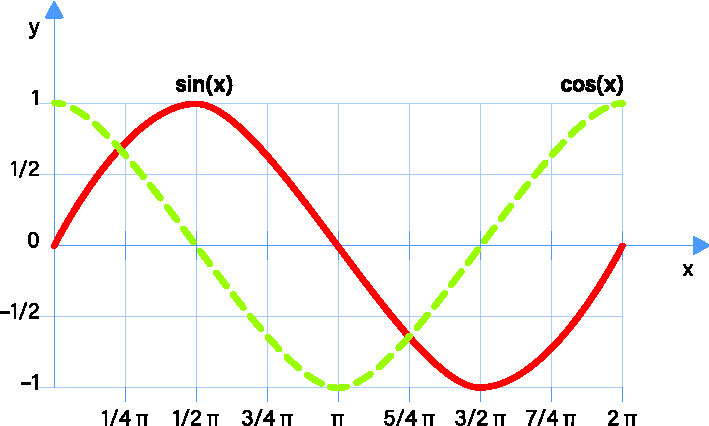
So I turned the coffee-mug apparatus around and entered the x- and y-axis readings into the Excel spreadsheet shown in Figure 3 (x-axis readings in blue, y-axis in red). If these values are compared with the ideal values shown in Figure 4, we can immediately see a discrepancy. The plots are of a sine and a cosine curve (or a sine curve shifted by 90 °). As we learned on our mother’s knee, in a right-angled triangle the sine of an angle is equal to the opposite over the hypotenuse, the cosine is equal to the adjacent divided by the hypotenuse, and the tangent is equal to the opposite divided by the adjacent; that means that the sine divided by the cosine is the tangent, as the hypotenuse cancels out. To determine the angle from the sides we need the inverse function, the arctangent, or arctan.
The Arduino libraries include an arctan2 function, which takes the x and y values as arguments. The nominal amplitudes of the x and y signals should be the same, but there is no need to normalize that amplitude to 1. Now we can see that the shift in the zero point is the cause of the problem. This also explains the bizarre recipe for calibrating a smartphone’s compass readings involving moving in figures of eight: clearly these smartphones use HMC magnetic sensors! In some cases I have heard that even this formula (or should I say ‘eight-mula’?) does not work, apparently because the deviation from the zero point is too great to be corrected.
It is also possible to calibrate the sensor ‘automatically’ in a similar way on the Arduino, deriving the required corrections from the maximum and minimum sensor readings. Writing the calibration values to the sensor requires two-way communication, which doubles the number of interface pins to two; since we have recorded the entire characteristic curve of the sensor, we can instead compute the necessary corrections in software and keep the wiring simple.
A New Program
A significant plus point of the original software is that it includes all the code needed to initialize and receive readings from the HMC device. I made a few changes to the monitor code to scale the readings to more manageable values by dividing them by 100: the NeoPixel ring only has 12 positions, so an accuracy of about ±10 % is plenty. If you plan to use a larger NeoPixel ring or a graphical display then you will need to retain the unscaled values and process them appropriately for the resolution you require. To drive the NeoPixels, I used a slimmed-down version of the very clearly-written code at [3], which seems suitable for driving twelve LEDs. The actual correction for the offset in the HMC sensor is shown in the source code snippet in Listing 1. The complete, and extensively modified, Arduino program can be downloaded at [4]. Of particular interest if you wish to experiment further with the code in the sketch is the monitor function.
Listing 1: Hard-coded calibration of the readings.x = x/100;
x = x+2;
Serial.print(x);
Serial.print(" Y Value: ");
y = y/100;
y = y+20;
Serial.print(y);
Serial.print(" Z Value: ");
z = z/100;
Serial.print(z);
Field Tests
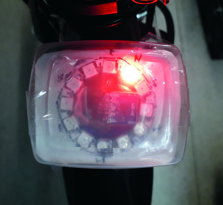
The compass should be built into a transparent plastic enclosure and mounted to the bicycle’s handlebars. Inside, construction is not critical: the various layers can be separated by plastic sheets, all fixed to a base plate using double-sided tape. A further plate, with an internal circular cutout and serrations can be used to fix the NeoPixel ring.
The calibration tests were carried out with LED 0 pointing towards north, but for some reason on testing the software it was found to light when the unit was pointing towards south. Rather than going in and changing the software to solve the problem properly, it was much simpler just to mount the unit on the bicycle such that to make LED 6 point straight ahead. Now, when the bicycle faces north, the ‘straight ahead’ LED lights; turn to the right, and the next LED to the left lights, again indicating the direction of north, just like it is supposed to.
Unfortunately it turned out that the residual magnetism in the steel of the handlebars upset the readings. However, I discovered (indirectly) that the frame of my bicycle is in fact made of aluminium: unlike steel, the properties of aluminium are such that it does not interfere with the compass. Because the unit is small, it was possible to attach it to the frame instead and keep it within my field of view (see Figure 5). Tests ‘in the field’ showed that the unit worked reliably, with the only problem occurring near to a railway bridge, probably caused by the field around the overhead wires; a subsequent test in the same location showed no error. So now, thanks to this compass, I can find my way around unfamiliar territory much more easily!
Questions the Project or the GY-271?
Do you have technical questions or comments about this article or the GY-271? Feel free to e-mail the Elektor editorial team at editor@elektor.com.
Discussion (0 comments)