The original goal was to build a receiver test circuit to pick up signals generated by the wheel rotation sensor. To start off with the TA7642 IC was used in its standard configuration. Initial testing was a bit of a headache but the outcome was that chip’s receiver sensitivity is influenced by the supply voltage. When the voltage at pin 3 is greater than a certain threshold the receiver can be easily overdriven. Using a preset pot it is easy to adjust this voltage and change the receiver sensitivity.
The most difficult part of the construction was going to be the antenna coil. The transmitter part of the bike computer is quite well encapsulated and difficult to dismantle without causing damage. I needed to find a quick and simple solution for the coil. Rummaging through a box of spare components I found some RFID coils still in their original packing. Result! The coils usually operate at a frequency of 125 kHz. They are generally operated in parallel with a 1 nF capacitor.
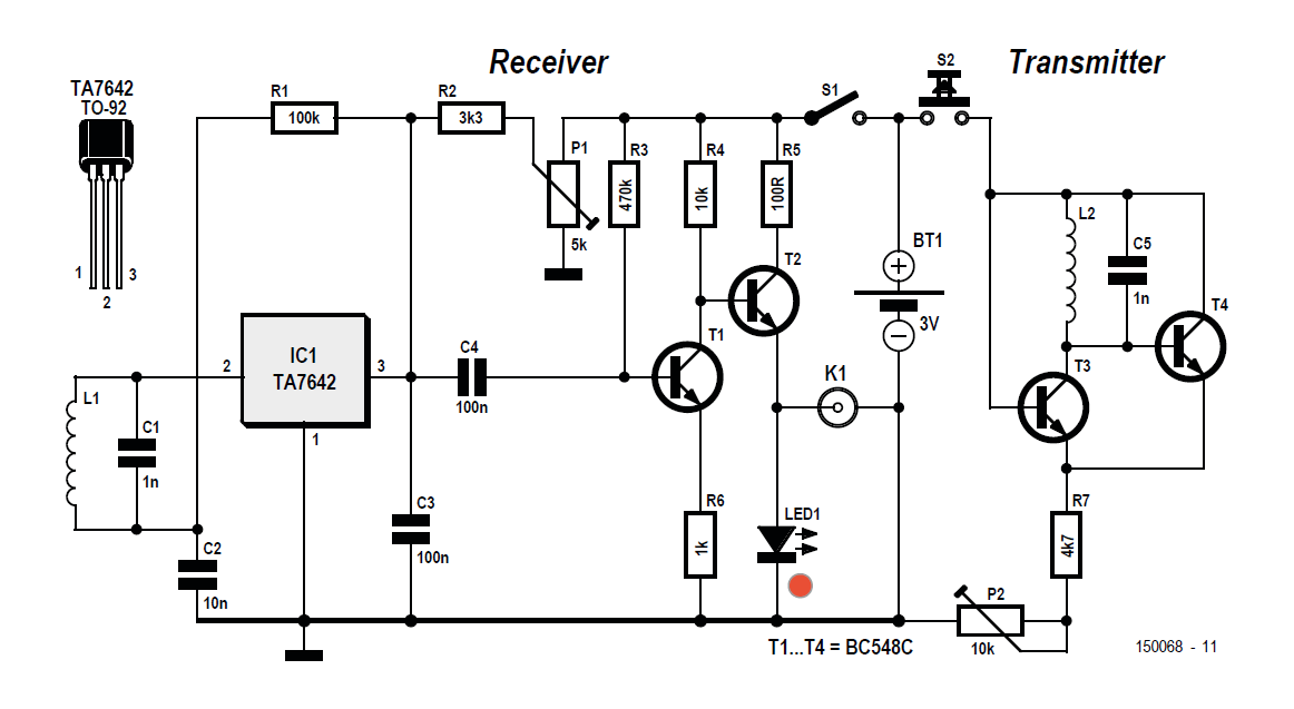
Figure 1. The diagnostic tool circuit uses a transmitter and receiver.
The test circuit
All the components were wired up using a prototyping plug board for simplicity and speed. The design for a two transistor amplifier circuit (T1 and T2 in Figure 1) is taken from a Philips application note for a headphone amplifier and adapted to drive the red LED. After the 3 V supply voltage has been connected it is necessary to adjust the operating point of the receiver IC. The voltage at pin 1 should be approximately 1 V. If the trimmer is adjusted so that the voltage on this pin is too high, the receiver will go into saturation and the LED comes on. For maximum sensitivity the trimmer is adjusted to a position just before the LED lights with no signal input. A piezo buzzer can be connected at K1 to make the received signal audible.
Once the receiver test circuit was up and running I tried to get the bike front wheel sensor to transmit by waving a magnet close to the sensor. There was no response at the receiver test circuit. I was fairly sure that the test receiver was working so now I needed to build a test transmitter circuit to generate the pulses to test the bike computer. I could get away with a simple oscillator circuit and an antenna coil here. It wasn’t necessary to make too many calculations I could just use the same coil used in the receiver circuit. Resistor R7 and preset P2 form the emitter resistance for T3 and T4. P2 can be adjusted to allow some fine-tuning of the oscillator frequency.
Elektor Magazine has been one of the leading sources of information on electronics for engineers, designers, start-ups and companies for 65 years. Our magazine is powered by an active community of electronics engineers – from students to professionals – who are passionate about designing and sharing innovative ideas.
For them, we publish hundreds of items a year, in formats such as articles, videos, webinars, and other learning formats. Our mission is to share knowledge in every possible way and inspire readers with the latest developments within the electrical engineering sector.
Thank you for your vote!
Leave further comments in the fields below.
Thank you for your vote!
If you wish to leave a comment with your rating, please first use the login below. If not, just close this window.

Discussion (0 comments)